Lantronix xPico xPico - Integration Guide - Page 17
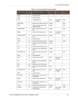
Table 2-4, xPico Wi-Fi PCB Interface Signals, Configurable I/O/ SPI Chip
 |
View all Lantronix xPico manuals
Add to My Manuals
Save this manual to your list of manuals |
Page 17 highlights
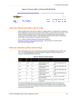
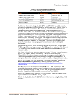
2: Functional Description Signal Name CP7 xPico Pin # 27 Primary Function Configurable I/O Reset State Input CP3 28 Configurable I/O Input 3V3 29 3.3V Input Power CP4 30 Configurable I/O Input 3V3 31 3.3V Input Power CP5 32 Configurable I/O Input 3V3 33 3.3V Input Power CP6 34 Configurable I/O Input CP1 35 Configurable I/O Input DEFAULT# GND EXT_RESET# GND GND 36 Unit reset to default, active low. Drive low to reset unit to default settings. Input 37 Signal Ground 38 Unit hardware reset, active Input low. Drive low to reboot unit. 39 Signal Ground 40 Signal Ground Internal Pull-up Active 56K to 122K Active 56K to 122K Driver Strength 4mA 4mA Active 56K 4mA to 122K 10K 4mA 10K Active 56K to 122K Active 56K to 122K 4mA 4mA 10K Table 2-4 xPico Wi-Fi PCB Interface Signals Signal Name xPico Primary Function Pin # GND 1 Signal Ground GND CP8/SPI_CS1 2 Signal Ground 3 Configurable I/O/ SPI Chip Select LED1/WLAN_LED 4 WLAN Link, active low RTS17 NC RXD1 5 Serial ready to send/ serial transmit enable 6 No Connect 7 Serial receive data input 1 NC GND TXD1 8 No Connect 9 Signal Ground 10 Serial transmit data output 1 Reset State Internal Pull-up /Pulldown Driver Strength Input, floating Input, floating Input, floating 30K to 50K 8mA 30K to 50K 8mA 30K to 50K 8mA Input, 30K to 50K floating Input, 30K to 50K 8mA xPico® Embedded Device Server Integration Guide 17
-
 1
1 -
2
-
3
-
4
-
5
-
6
-
7
-
8
-
9
-
10
-
11
-
 12
12 -
 13
13 -
 14
14 -
 15
15 -
 16
16 -
 17
17 -
 18
18 -
 19
19 -
 20
20 -
 21
21 -
 22
22 -
23
-
24
-
25
-
26
-
27
-
28
-
29
-
30
-
31
-
32
-
33
-
34
-
35
-
36
-
37
-
38
-
39
-
40
-
41
-
42
-
43
-
44
-
45
-
46
-
47
-
48
-
49
-
50
-
51
-
52
 |
 |
