Lantronix xPico xPico - Integration Guide - Page 21
Antenna Placement (xPico Wi-Fi only), Ethernet Interface (xPico wired only)
 |
View all Lantronix xPico manuals
Add to My Manuals
Save this manual to your list of manuals |
Page 21 highlights
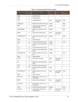
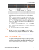
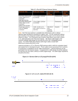
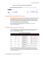
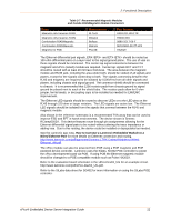
2: Functional Description Figure 2-6 Reverse-SMA to U.FL(short) (P/N 500-182-R) Antenna Placement (xPico Wi-Fi only) When designing the xPico Wi-Fi module to a mating board, it is important to consider the final installation of the unit and its location with respect to connecting access points. The antenna should be placed so that it has as clear as possible path to the connecting access point for maximum range. Avoid placing the antenna such that it is blocked by metal walls or ground planes of adjacent circuit boards. Note: Refer to antenna placement instructions located at http://www.lantronix.com/support/downloads/. This document is located under the xPico Wi-Fi product line. Ethernet Interface (xPico wired only) xPico embedded device server integrates an internal 10/100Mbps Ethernet MAC and PHY. An external magnetic module and RJ45 is required in order to connect to a standard 10/100Mbps Ethernet network. Table 2-6 Ethernet Interface Signals Signal Name DIR Contact Primary Function Signal Requirement TX+ Out 13 Differential Ethernet 100 ohm differential with transmit data + TX- TX- Out 11 Differential Ethernet 100 ohm differential with transmit data - TX+ RX+ In 19 Differential Ethernet 100 ohm differential with receive data + RX- RX- In 17 Differential Ethernet 100 ohm differential with receive data - RX+ TCT 12 Ethernet transmit center Route > 20 mil width tap connection RCT 18 Ethernet receive center tap Route > 20 mil width connection The xPico embedded device server provides a 10/100 Mbps Ethernet interface for connection to an external network through external magnetics and an external RJ45. The table below lists several magnetic modules and combination RJ45/magnetic jacks that can be used with xPico. xPico® Embedded Device Server Integration Guide 21
-
 1
1 -
2
-
3
-
4
-
5
-
6
-
7
-
8
-
9
-
10
-
11
-
12
-
13
-
14
-
15
-
 16
16 -
 17
17 -
 18
18 -
 19
19 -
 20
20 -
 21
21 -
 22
22 -
 23
23 -
 24
24 -
 25
25 -
 26
26 -
27
-
28
-
29
-
30
-
31
-
32
-
33
-
34
-
35
-
36
-
37
-
38
-
39
-
40
-
41
-
42
-
43
-
44
-
45
-
46
-
47
-
48
-
49
-
50
-
51
-
52
 |
 |
