Lantronix xPico xPico - Integration Guide - Page 14
xPico Wi-Fi Block Diagram
 |
View all Lantronix xPico manuals
Add to My Manuals
Save this manual to your list of manuals |
Page 14 highlights
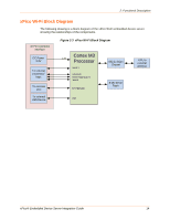
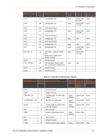
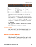
2: Functional Description xPico Wi-Fi Block Diagram The following drawing is a block diagram of the xPico Wi-Fi embedded device server showing the relationships of the components. 40 Pin Connector Interface DC Power 3.3V To external processor/ logic To external LED To external USB Device Figure 2-3 xPico Wi-Fi Block Diagram Cortex M3 3.3V Processor Serial 1 GPIO/SPI RESET/DEFAULTS WAKE SYSTEM LED USB 802.11 b/g/n Chipset 8 Mb Serial Flash U.FL to external antenna xPico® Embedded Device Server Integration Guide 14
-
 1
1 -
2
-
3
-
4
-
5
-
6
-
7
-
8
-
 9
9 -
 10
10 -
 11
11 -
 12
12 -
 13
13 -
 14
14 -
 15
15 -
 16
16 -
 17
17 -
 18
18 -
 19
19 -
20
-
21
-
22
-
23
-
24
-
25
-
26
-
27
-
28
-
29
-
30
-
31
-
32
-
33
-
34
-
35
-
36
-
37
-
38
-
39
-
40
-
41
-
42
-
43
-
44
-
45
-
46
-
47
-
48
-
49
-
50
-
51
-
52
 |
 |

2: Functional Description
xPico Wi-Fi Block Diagram
The following drawing is a block diagram of the xPico Wi-Fi embedded device server
showing the relationships of the components.
Figure 2-3
xPico Wi-Fi Block Diagram
DC Power
3.3V
8 Mb Serial
Flash
Cortex M3
Processor
To external
USB Device
3.3V
Serial 1
GPIO/SPI
40 Pin Connector
Interface
USB
To external
processor/
logic
To external
LED
SYSTEM LED
RESET/DEFAULTS
WAKE
802.11 b/g/n
Chipset
U.FL to
external
antenna
xPico® Embedded Device Server Integration Guide
14