Lenovo H520g Lenovo H520g Hardware Maintenance Manual - Page 93
Reconnect all remaining cables to the system board. See Locating parts on the system board
 |
View all Lenovo H520g manuals
Add to My Manuals
Save this manual to your list of manuals |
Page 93 highlights
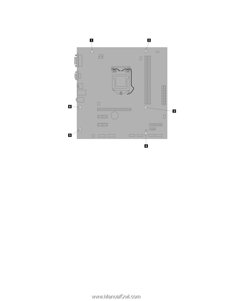
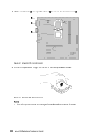
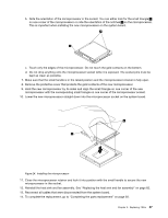
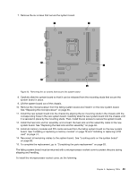
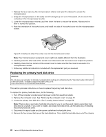
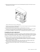
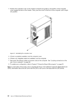
7. Remove the six screws that secure the system board. Figure 25. Removing the six screws that secure the system board 8. Carefully slide the system board so that it can be released from the mounting studs that secure the system board in place. 9. Lift the system board out of the chassis. 10. Remove the microprocessor from the failing system board and install it on the new system board. See "Replacing the microprocessor" on page 85. 11. Install the new system board into the chassis by aligning the six mounting studs in the chassis with the corresponding holes in the new system board. Carefully slide the new system board into the chassis until it is secured in place by the mounting studs. Then, install the six screws to secure the system board. 12. Install the heat sink and fan assembly and connect the heat sink and fan assembly cable to the new system board. See "Replacing the heat sink and fan assembly" on page 82. 13. Install all memory modules and PCI cards removed from the failing system board on the new system board. See "Installing or replacing a memory module" on page 78 and "Installing or replacing a PCI card" on page 74. 14. Reconnect all remaining cables to the system board. See "Locating parts on the system board" on page 68. 15. To complete the replacement, go to "Completing the parts replacement" on page 93. The failing system board must be returned with a microprocessor socket cover to protect the pins during shipping and handling. To install the microprocessor socket cover, do the following: Chapter 9. Replacing FRUs 89
-
 1
1 -
2
-
3
-
4
-
5
-
6
-
7
-
8
-
9
-
10
-
11
-
12
-
13
-
14
-
15
-
16
-
17
-
18
-
19
-
20
-
21
-
22
-
23
-
24
-
25
-
26
-
27
-
28
-
29
-
30
-
31
-
32
-
33
-
34
-
35
-
36
-
37
-
38
-
39
-
40
-
41
-
42
-
43
-
44
-
45
-
46
-
47
-
48
-
49
-
50
-
51
-
52
-
53
-
54
-
55
-
56
-
57
-
58
-
59
-
60
-
61
-
62
-
63
-
64
-
65
-
66
-
67
-
68
-
69
-
70
-
71
-
72
-
73
-
74
-
75
-
76
-
77
-
78
-
79
-
80
-
81
-
82
-
83
-
84
-
85
-
86
-
87
-
 88
88 -
 89
89 -
 90
90 -
 91
91 -
 92
92 -
 93
93 -
 94
94 -
 95
95 -
 96
96 -
 97
97 -
 98
98 -
99
-
100
-
101
-
102
-
103
-
104
-
105
-
106
-
107
-
108
-
109
-
110
-
111
-
112
 |
 |