Lenovo PC 300PL Installing Options in your PC300PL - 6562 - Page 23
Locating Components, Internal View
 |
View all Lenovo PC 300PL manuals
Add to My Manuals
Save this manual to your list of manuals |
Page 23 highlights
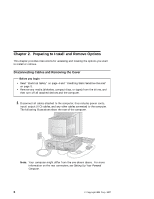
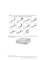
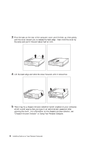
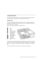
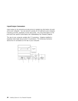
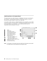
Locating Components The following information helps you locate components and serves as a reference when you need to install options or connect input/output devices. Internal View The following illustration shows the internal view of your computer as seen from the front. For information on removing the cover, see "Disconnecting Cables and Removing the Cover" on page 6. Note: The following illustration is for reference only. 1 Bay 1 14 2 Bay 2 3 Bay 3 4 Bay 4 5 Volume control knob 6 Headphone out jack 7 Microphone in jack 8 Chassis intrusion detection switch 9 Client LAN light 1 Hard disk drive light 13 11 Power-on light 12 On-off switch 13 System board 14 Riser card expansion slots 12 11 10 9 8 1 765 4 3 2 Your computer comes with a diskette drive installed in bay 4 and a hard disk drive installed in bay 3. If your computer comes with a CD-ROM drive, it is installed in bay 1; if your computer comes with a SCSI adapter, it is installed in an expansion slot. For more information on drive bays, see "Internal Drives" on page 39. Chapter 2. Preparing to Install and Remove Options 9
-
 1
1 -
2
-
3
-
4
-
5
-
6
-
7
-
8
-
9
-
10
-
11
-
12
-
13
-
14
-
15
-
16
-
17
-
 18
18 -
 19
19 -
 20
20 -
 21
21 -
 22
22 -
 23
23 -
 24
24 -
 25
25 -
 26
26 -
 27
27 -
 28
28 -
29
-
30
-
31
-
32
-
33
-
34
-
35
-
36
-
37
-
38
-
39
-
40
-
41
-
42
-
43
-
44
-
45
-
46
-
47
-
48
-
49
-
50
-
51
-
52
-
53
-
54
-
55
-
56
-
57
-
58
-
59
-
60
-
61
-
62
-
63
-
64
-
65
-
66
-
67
-
68
-
69
-
70
-
71
-
72
-
73
-
74
-
75
-
76
-
77
-
78
-
79
-
80
-
81
-
82
-
83
-
84
-
85
-
86
-
87
-
88
-
89
-
90
-
91
-
92
-
93
-
94
-
95
-
96
-
97
-
98
-
99
-
100
 |
 |
