Lenovo ThinkCentre M76 (English) User Guide - Page 40
Remove the computer cover. See Removing the computer cover on Lift the small handle
 |
View all Lenovo ThinkCentre M76 manuals
Add to My Manuals
Save this manual to your list of manuals |
Page 40 highlights
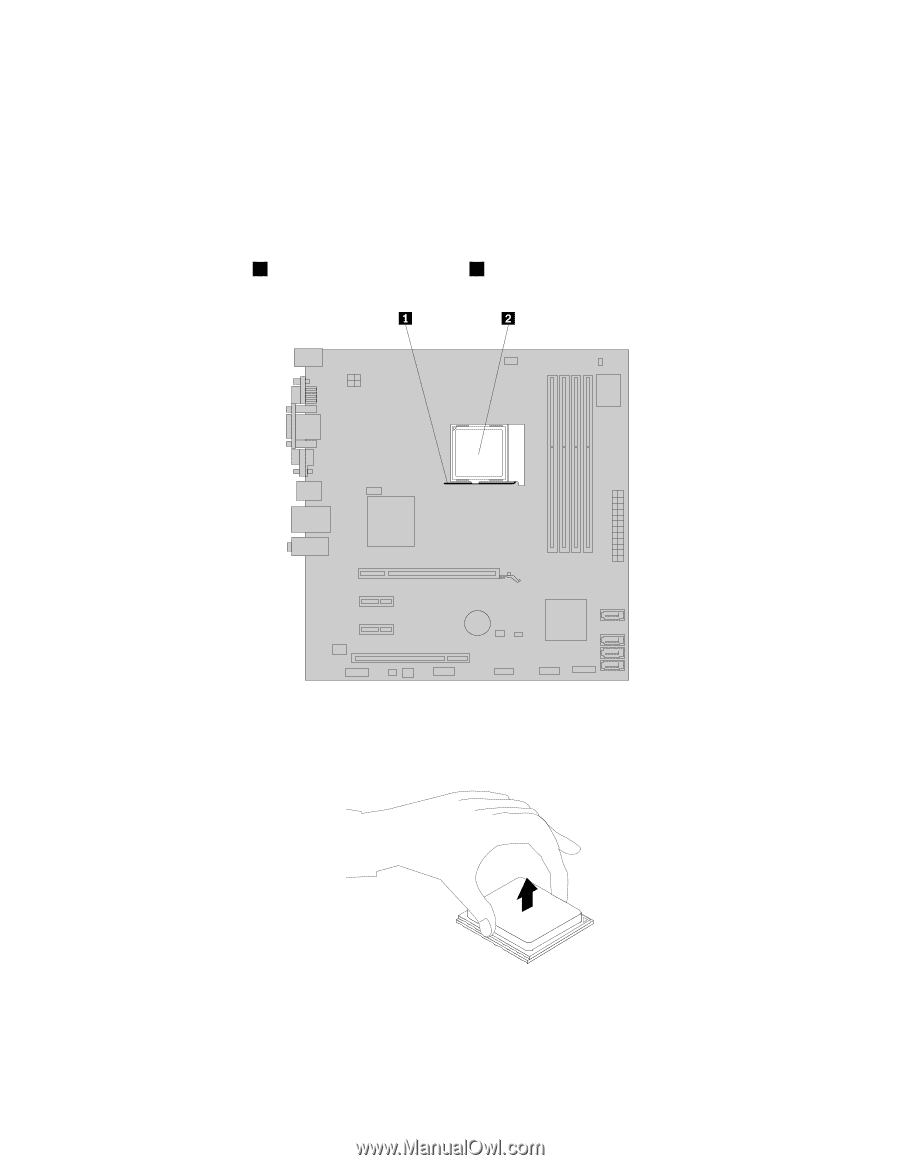
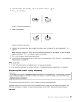
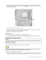
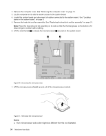
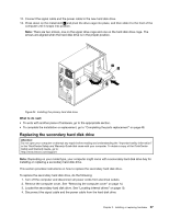
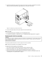
2. Remove the computer cover. See "Removing the computer cover" on page 14. 3. Lay the computer on its side for easier access to the system board. 4. Locate the system board and disconnect all cables connected to the system board. See "Locating parts on the system board" on page 9. 5. Remove the heat sink and fan assembly. See "Replacing the heat sink and fan assembly" on page 31. Note: Place the heat sink and fan assembly on its side so that the thermal grease on the bottom of it does not get in contact with anything. 6. Lift the small handle 1 to release the microprocessor 2 secured on the system board. Figure 30. Accessing the microprocessor 7. Lift the microprocessor straight up and out of the microprocessor socket. Figure 31. Removing the microprocessor Notes: a. Your microprocessor and socket might look different from the one illustrated. 34 ThinkCentre User Guide
-
 1
1 -
2
-
3
-
4
-
5
-
6
-
7
-
8
-
9
-
10
-
11
-
12
-
13
-
14
-
15
-
16
-
17
-
18
-
19
-
20
-
21
-
22
-
23
-
24
-
25
-
26
-
27
-
28
-
29
-
30
-
31
-
32
-
33
-
34
-
 35
35 -
 36
36 -
 37
37 -
 38
38 -
 39
39 -
 40
40 -
 41
41 -
 42
42 -
 43
43 -
 44
44 -
 45
45 -
46
-
47
-
48
-
49
-
50
-
51
-
52
-
53
-
54
-
55
-
56
-
57
-
58
-
59
-
60
-
61
-
62
-
63
-
64
-
65
-
66
-
67
-
68
-
69
-
70
-
71
-
72
-
73
-
74
-
75
-
76
-
77
-
78
-
79
-
80
-
81
-
82
-
83
-
84
-
85
-
86
-
87
-
88
-
89
-
90
-
91
-
92
 |
 |