Lenovo ThinkCentre M80 Hardware Maintenance Manual for ThinkCentre M80 - Page 107
the Setup Utility program. See Using the Setup Utility program
 |
View all Lenovo ThinkCentre M80 manuals
Add to My Manuals
Save this manual to your list of manuals |
Page 107 highlights
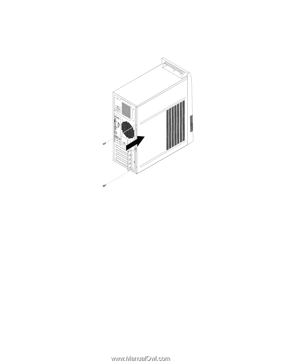
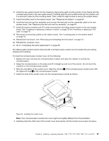
4. Position the computer cover on the chassis so that the rail guides on the bottom of the computer cover engage the rails. Then, slide the computer cover to the front of the computer until it snaps into position and is closed. Then, install the two screws to secure the computer cover. Figure 35. Reinstalling the computer cover 5. Lock the computer cover if you have a computer cover lock. 6. Reconnect the power cord and all other external cables to the computer. For connector locations, see "Locating connectors, controls, and indicators on the front of your computer" on page 67 and "Locating connectors and parts on the rear of your computer" on page 68. 7. Depending on the parts you installed or replaced, you might need to confirm the updated information in the Setup Utility program. See Chapter 6 "Using the Setup Utility program" on page 39. Note: In most areas of the world, Lenovo requires the return of the defective Customer Replaceable Units (CRUs). Information about this will come with the new CRUs or will come a few days after you receive the new CRUs. Chapter 8. Installing or replacing hardware: 4165, 7179, 7182, 7490, 7493, 7511, and 7521 99
-
 1
1 -
2
-
3
-
4
-
5
-
6
-
7
-
8
-
9
-
10
-
11
-
12
-
13
-
14
-
15
-
16
-
17
-
18
-
19
-
20
-
21
-
22
-
23
-
24
-
25
-
26
-
27
-
28
-
29
-
30
-
31
-
32
-
33
-
34
-
35
-
36
-
37
-
38
-
39
-
40
-
41
-
42
-
43
-
44
-
45
-
46
-
47
-
48
-
49
-
50
-
51
-
52
-
53
-
54
-
55
-
56
-
57
-
58
-
59
-
60
-
61
-
62
-
63
-
64
-
65
-
66
-
67
-
68
-
69
-
70
-
71
-
72
-
73
-
74
-
75
-
76
-
77
-
78
-
79
-
80
-
81
-
82
-
83
-
84
-
85
-
86
-
87
-
88
-
89
-
90
-
91
-
92
-
93
-
94
-
95
-
96
-
97
-
98
-
99
-
100
-
101
-
 102
102 -
 103
103 -
 104
104 -
 105
105 -
 106
106 -
 107
107 -
 108
108 -
 109
109 -
 110
110 -
 111
111 -
 112
112 -
113
-
114
-
115
-
116
-
117
-
118
-
119
-
120
-
121
-
122
-
123
-
124
-
125
-
126
-
127
-
128
-
129
-
130
-
131
-
132
-
133
-
134
-
135
-
136
-
137
-
138
-
139
-
140
-
141
-
142
-
143
-
144
-
145
-
146
-
147
-
148
-
149
-
150
-
151
-
152
-
153
-
154
-
155
-
156
-
157
-
158
-
159
-
160
-
161
-
162
-
163
-
164
-
165
-
166
-
167
-
168
-
169
-
170
-
171
-
172
-
173
-
174
-
175
-
176
-
177
-
178
-
179
-
180
-
181
-
182
-
183
-
184
-
185
-
186
-
187
-
188
-
189
-
190
-
191
-
192
-
193
-
194
-
195
-
196
-
197
-
198
-
199
-
200
-
201
-
202
-
203
-
204
-
205
-
206
-
207
-
208
-
209
-
210
-
211
-
212
-
213
-
214
-
215
-
216
-
217
-
218
-
219
-
220
-
221
-
222
-
223
-
224
-
225
-
226
-
227
-
228
-
229
-
230
-
231
-
232
-
233
-
234
-
235
-
236
-
237
-
238
-
239
-
240
-
241
-
242
-
243
-
244
-
245
-
246
-
247
-
248
-
249
-
250
-
251
-
252
-
253
-
254
-
255
-
256
-
257
-
258
-
259
-
260
-
261
-
262
-
263
-
264
-
265
-
266
-
267
-
268
-
269
-
270
-
271
-
272
-
273
-
274
-
275
-
276
-
277
-
278
-
279
-
280
-
281
-
282
 |
 |