Lenovo ThinkCentre M80 Hardware Maintenance Manual for ThinkCentre M80 - Page 144
board. See Installing or replacing a memory module on and Installing or replacing a PCI
 |
View all Lenovo ThinkCentre M80 manuals
Add to My Manuals
Save this manual to your list of manuals |
Page 144 highlights
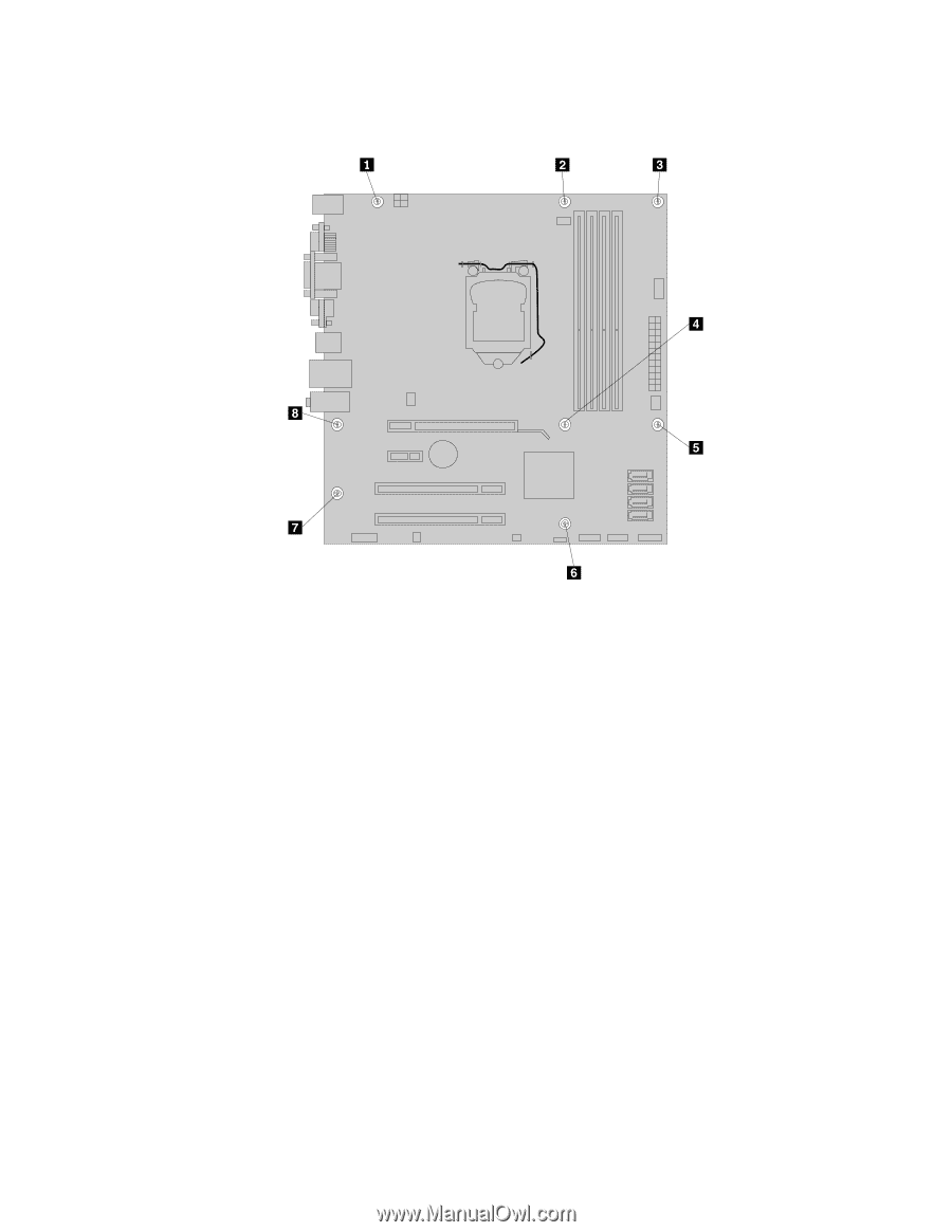
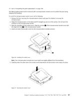
10. Remove the eight screws that secure the system board. Figure 75. Removing the eight screws that secure the system board 11. Lift the system board out of the chassis. 12. Remove the microprocessor from the failing system board and install it on the new system board. See "Replacing the microprocessor" on page 119. Note: If your new system board comes with a microprocessor socket cover, remove the socket cover before you install the microprocessor on the new system board. 13. Install the new system board into the chassis by aligning the eight mounting studs in the chassis with the corresponding holes in the new system board. Then, install the eight screws to secure the system board. 14. Install the battery back to the system board. See "Replacing the battery" on page 115. 15. Install the heat sink and fan assembly and connect the heat sink and fan assembly cable to the new system board. See "Replacing the heat sink and fan assembly" on page 116. 16. Install all memory modules and PCI cards removed from the failing system board on the new system board. See "Installing or replacing a memory module" on page 113 and "Installing or replacing a PCI card" on page 110. 17. Reconnect all remaining cables to the system board. See "Locating parts on the system board" on page 104. 18. Lower the drive bay assembly. See "Accessing the system board components and drives" on page 109. 19. Reinstall the front bezel. See "Removing and reinstalling the front bezel" on page 108. 20. Reinstall the computer cover. 136 ThinkCentre Hardware Maintenance Manual
-
 1
1 -
2
-
3
-
4
-
5
-
6
-
7
-
8
-
9
-
10
-
11
-
12
-
13
-
14
-
15
-
16
-
17
-
18
-
19
-
20
-
21
-
22
-
23
-
24
-
25
-
26
-
27
-
28
-
29
-
30
-
31
-
32
-
33
-
34
-
35
-
36
-
37
-
38
-
39
-
40
-
41
-
42
-
43
-
44
-
45
-
46
-
47
-
48
-
49
-
50
-
51
-
52
-
53
-
54
-
55
-
56
-
57
-
58
-
59
-
60
-
61
-
62
-
63
-
64
-
65
-
66
-
67
-
68
-
69
-
70
-
71
-
72
-
73
-
74
-
75
-
76
-
77
-
78
-
79
-
80
-
81
-
82
-
83
-
84
-
85
-
86
-
87
-
88
-
89
-
90
-
91
-
92
-
93
-
94
-
95
-
96
-
97
-
98
-
99
-
100
-
101
-
102
-
103
-
104
-
105
-
106
-
107
-
108
-
109
-
110
-
111
-
112
-
113
-
114
-
115
-
116
-
117
-
118
-
119
-
120
-
121
-
122
-
123
-
124
-
125
-
126
-
127
-
128
-
129
-
130
-
131
-
132
-
133
-
134
-
135
-
136
-
137
-
138
-
 139
139 -
 140
140 -
 141
141 -
 142
142 -
 143
143 -
 144
144 -
 145
145 -
 146
146 -
 147
147 -
 148
148 -
 149
149 -
150
-
151
-
152
-
153
-
154
-
155
-
156
-
157
-
158
-
159
-
160
-
161
-
162
-
163
-
164
-
165
-
166
-
167
-
168
-
169
-
170
-
171
-
172
-
173
-
174
-
175
-
176
-
177
-
178
-
179
-
180
-
181
-
182
-
183
-
184
-
185
-
186
-
187
-
188
-
189
-
190
-
191
-
192
-
193
-
194
-
195
-
196
-
197
-
198
-
199
-
200
-
201
-
202
-
203
-
204
-
205
-
206
-
207
-
208
-
209
-
210
-
211
-
212
-
213
-
214
-
215
-
216
-
217
-
218
-
219
-
220
-
221
-
222
-
223
-
224
-
225
-
226
-
227
-
228
-
229
-
230
-
231
-
232
-
233
-
234
-
235
-
236
-
237
-
238
-
239
-
240
-
241
-
242
-
243
-
244
-
245
-
246
-
247
-
248
-
249
-
250
-
251
-
252
-
253
-
254
-
255
-
256
-
257
-
258
-
259
-
260
-
261
-
262
-
263
-
264
-
265
-
266
-
267
-
268
-
269
-
270
-
271
-
272
-
273
-
274
-
275
-
276
-
277
-
278
-
279
-
280
-
281
-
282
 |
 |