Lenovo ThinkCentre M80 Hardware Maintenance Manual for ThinkCentre M80 - Page 133
Installing the heat sink fan duct, ThinkCentre Safety and Warranty Guide, ThinkCentre
 |
View all Lenovo ThinkCentre M80 manuals
Add to My Manuals
Save this manual to your list of manuals |
Page 133 highlights
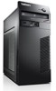
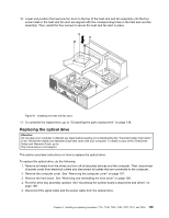
10. Lower and position the heat sink fan duct on the top of the heat sink and fan assembly until the four screw holes in the heat sink fan duct are aligned with the corresponding holes in the heat sink and fan assembly. Then, install the four screws to secure the heat sink fan duct in place. Figure 61. Installing the heat sink fan duct 11. To complete the replacement, go to "Completing the parts replacement" on page 138. Replacing the optical drive Attention: Do not open your computer or attempt any repair before reading and understanding the "Important safety information" in the ThinkCentre Safety and Warranty Guide that came with your computer. To obtain a copy of the ThinkCentre Safety and Warranty Guide, go to: http://www.lenovo.com/support This section provides instructions on how to replace the optical drive. To replace the optical drive, do the following: 1. Remove all media from the drives and turn off all attached devices and the computer. Then, disconnect all power cords from electrical outlets and disconnect all cables that are connected to the computer. 2. Remove the computer cover. See "Removing the computer cover" on page 107. 3. Remove the front bezel. See "Removing and reinstalling the front bezel" on page 108. 4. Pivot the drive bay assembly upward. See "Accessing the system board components and drives" on page 109. 5. Disconnect the signal cable and the power cable from the optical drive. Chapter 9. Installing or replacing hardware: 7181, 7189, 7239, 7492, 7507, 7513, and 7529 125
-
 1
1 -
2
-
3
-
4
-
5
-
6
-
7
-
8
-
9
-
10
-
11
-
12
-
13
-
14
-
15
-
16
-
17
-
18
-
19
-
20
-
21
-
22
-
23
-
24
-
25
-
26
-
27
-
28
-
29
-
30
-
31
-
32
-
33
-
34
-
35
-
36
-
37
-
38
-
39
-
40
-
41
-
42
-
43
-
44
-
45
-
46
-
47
-
48
-
49
-
50
-
51
-
52
-
53
-
54
-
55
-
56
-
57
-
58
-
59
-
60
-
61
-
62
-
63
-
64
-
65
-
66
-
67
-
68
-
69
-
70
-
71
-
72
-
73
-
74
-
75
-
76
-
77
-
78
-
79
-
80
-
81
-
82
-
83
-
84
-
85
-
86
-
87
-
88
-
89
-
90
-
91
-
92
-
93
-
94
-
95
-
96
-
97
-
98
-
99
-
100
-
101
-
102
-
103
-
104
-
105
-
106
-
107
-
108
-
109
-
110
-
111
-
112
-
113
-
114
-
115
-
116
-
117
-
118
-
119
-
120
-
121
-
122
-
123
-
124
-
125
-
126
-
127
-
 128
128 -
 129
129 -
 130
130 -
 131
131 -
 132
132 -
 133
133 -
 134
134 -
 135
135 -
 136
136 -
 137
137 -
 138
138 -
139
-
140
-
141
-
142
-
143
-
144
-
145
-
146
-
147
-
148
-
149
-
150
-
151
-
152
-
153
-
154
-
155
-
156
-
157
-
158
-
159
-
160
-
161
-
162
-
163
-
164
-
165
-
166
-
167
-
168
-
169
-
170
-
171
-
172
-
173
-
174
-
175
-
176
-
177
-
178
-
179
-
180
-
181
-
182
-
183
-
184
-
185
-
186
-
187
-
188
-
189
-
190
-
191
-
192
-
193
-
194
-
195
-
196
-
197
-
198
-
199
-
200
-
201
-
202
-
203
-
204
-
205
-
206
-
207
-
208
-
209
-
210
-
211
-
212
-
213
-
214
-
215
-
216
-
217
-
218
-
219
-
220
-
221
-
222
-
223
-
224
-
225
-
226
-
227
-
228
-
229
-
230
-
231
-
232
-
233
-
234
-
235
-
236
-
237
-
238
-
239
-
240
-
241
-
242
-
243
-
244
-
245
-
246
-
247
-
248
-
249
-
250
-
251
-
252
-
253
-
254
-
255
-
256
-
257
-
258
-
259
-
260
-
261
-
262
-
263
-
264
-
265
-
266
-
267
-
268
-
269
-
270
-
271
-
272
-
273
-
274
-
275
-
276
-
277
-
278
-
279
-
280
-
281
-
282
 |
 |
