Lenovo ThinkServer RD240 (English) Installation and User Guide - Page 100
Starting the Configuration Utility program
 |
View all Lenovo ThinkServer RD240 manuals
Add to My Manuals
Save this manual to your list of manuals |
Page 100 highlights
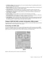
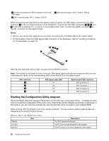
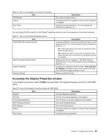
1 J51 (for connecting the SGPIO connector of the mini SAS cable) 2 SAS connectors (top: SAS 1; bottom: SAS 0) 3 SAS connectors (top: SAS 3; bottom: SAS 2) When connecting hard disk drives to the system board using the mini SAS cable, connect the mini SAS connector 4 to the mini SAS connector on the backplane. Connect the four SAS connectors 6 , 7 , 8 , and 9 to the SAS connectors 0, 1, 2, and 3 on the system board. Then, connect the SGPIO connector 5 to the J51 connector on the system board. Notes: • Remove any device that might prevent you from connecting the mini SAS cable to the system board. • For the location of the mini-SAS signal cable connector on the backplane, refer to "Locating connectors on the backplane" on page 18. Figure 66. Mini SAS cable with four SAS connectors and one SGPIO connector Note: The number on the label for each of the four SAS signal cables indicates the sequence when you are connecting the cables to the corresponding SAS connectors (0-3) on the system board. SAS connector 6 7 8 9 SAS signal cable label P1 P2 P3 P4 System board SAS connector SAS connector 0 SAS connector 1 SAS connector 2 SAS connector 3 Starting the Configuration Utility program During the POST, when the message "Press Ctrl-C to start LSI Logic configuration Utility..." is displayed, press Ctrl+C to enter the Configuration Utility main menu. Press Enter and the Adapter List window is displayed. In this window, you can view the controller list, view the hard disk drive information, and configure RAID. When working with this program, you must use the keyboard. The keys used to perform various tasks are displayed at the bottom of each screen. Table 26. Items in the Adapter List window Item Adapter PCI Bus Dev/Fnc Description The SAS adapter(s) detected The PCI bus number assigned to the adapter The PCI device or function assigned to the adapter 88 ThinkServer User Guide
-
 1
1 -
2
-
3
-
4
-
5
-
6
-
7
-
8
-
9
-
10
-
11
-
12
-
13
-
14
-
15
-
16
-
17
-
18
-
19
-
20
-
21
-
22
-
23
-
24
-
25
-
26
-
27
-
28
-
29
-
30
-
31
-
32
-
33
-
34
-
35
-
36
-
37
-
38
-
39
-
40
-
41
-
42
-
43
-
44
-
45
-
46
-
47
-
48
-
49
-
50
-
51
-
52
-
53
-
54
-
55
-
56
-
57
-
58
-
59
-
60
-
61
-
62
-
63
-
64
-
65
-
66
-
67
-
68
-
69
-
70
-
71
-
72
-
73
-
74
-
75
-
76
-
77
-
78
-
79
-
80
-
81
-
82
-
83
-
84
-
85
-
86
-
87
-
88
-
89
-
90
-
91
-
92
-
93
-
94
-
 95
95 -
 96
96 -
 97
97 -
 98
98 -
 99
99 -
 100
100 -
 101
101 -
 102
102 -
 103
103 -
 104
104 -
 105
105 -
106
-
107
-
108
-
109
-
110
-
111
-
112
-
113
-
114
-
115
-
116
-
117
-
118
-
119
-
120
-
121
-
122
-
123
-
124
-
125
-
126
-
127
-
128
-
129
-
130
-
131
-
132
-
133
-
134
-
135
-
136
-
137
-
138
-
139
-
140
 |
 |
