Lenovo ThinkServer RD240 (English) Installation and User Guide - Page 25
connector on the system board. See Locating parts on the system board - alarm
 |
View all Lenovo ThinkServer RD240 manuals
Add to My Manuals
Save this manual to your list of manuals |
Page 25 highlights
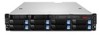
The following table describes the meaning of the LEDs on the front control panel. Table 3. Front control panel LEDs LED State ID LED On Off System status Off LED On Ethernet 1 status LED Ethernet 2 status LED Power status LED Blinking On Off Blinking On Off On Blinking Off Color Blue Off Off Red Green Green Off Green Green Off Green Green Off Description ID is on. ID is off. System is normal. • Fan alarm • Voltage alarm • Temperature alarm LAN is active and data is being transferred. LAN is connected. LAN is not connected. LAN is active and data is being transferred. LAN is connected. LAN is not connected. Power is on. The server power is under S1 mode. Power is off. Each hard disk drive also has two status LEDs. Status LED 1 (top) indicates presence (whether the drive is recognized by the system) and Status LED 2 (bottom) indicates drive activity. Notes: • If the onboard SAS and onboard 1068E SAS RAID controller are configured, note the following: - The SGPIO connector of the 4-port mini-SAS cable in the chassis should be connected to the J51 connector on the system board. See "Locating parts on the system board" on page 16. Table 4. Hard disk drive LEDs for the onboard 1068E SAS RAID controller and add-on SAS RAID adapter configurations Description Hard disk drive status LED 1 Hard disk drive status LED 2 Hard disk drive is not present. Off Off Hard disk drive is present but is not active. Off Green (for SATA hard disk drives, the status is Off) Hard disk drive is present and active. Off Blinking green Server is in the process of locating the hard disk drive. Blinking green Green Hard disk drive has failed. Red Green RAID is rebuilding. Blinking red Green The Ethernet 1 and Ethernet 2 connectors have two status LEDs that indicate the LAN connection and activity of the connection. Chapter 4. Locating parts, controls, LEDs, and connectors 13
-
 1
1 -
2
-
3
-
4
-
5
-
6
-
7
-
8
-
9
-
10
-
11
-
12
-
13
-
14
-
15
-
16
-
17
-
18
-
19
-
 20
20 -
 21
21 -
 22
22 -
 23
23 -
 24
24 -
 25
25 -
 26
26 -
 27
27 -
 28
28 -
 29
29 -
 30
30 -
31
-
32
-
33
-
34
-
35
-
36
-
37
-
38
-
39
-
40
-
41
-
42
-
43
-
44
-
45
-
46
-
47
-
48
-
49
-
50
-
51
-
52
-
53
-
54
-
55
-
56
-
57
-
58
-
59
-
60
-
61
-
62
-
63
-
64
-
65
-
66
-
67
-
68
-
69
-
70
-
71
-
72
-
73
-
74
-
75
-
76
-
77
-
78
-
79
-
80
-
81
-
82
-
83
-
84
-
85
-
86
-
87
-
88
-
89
-
90
-
91
-
92
-
93
-
94
-
95
-
96
-
97
-
98
-
99
-
100
-
101
-
102
-
103
-
104
-
105
-
106
-
107
-
108
-
109
-
110
-
111
-
112
-
113
-
114
-
115
-
116
-
117
-
118
-
119
-
120
-
121
-
122
-
123
-
124
-
125
-
126
-
127
-
128
-
129
-
130
-
131
-
132
-
133
-
134
-
135
-
136
-
137
-
138
-
139
-
140
 |
 |
