Lenovo ThinkServer RD240 (English) Installation and User Guide - Page 24
Front control panel, The following illustration helps you identify the connectors, controls
 |
View all Lenovo ThinkServer RD240 manuals
Add to My Manuals
Save this manual to your list of manuals |
Page 24 highlights
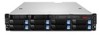
4 USB connectors (1 and 2) 5 VGA monitor connector Connector Power cord connector Ethernet connector Serial port USB connector VGA monitor connector 9 Ethernet connector 2 (share with MGMT) 10 PCI expansion slot Description Used to connect the power cord. Used to attach an Ethernet cable for a local area network (LAN). Used to attach a device that uses a 9-pin serial port. Used to attach a device that uses a USB connector, such as a USB keyboard or a USB mouse. Used to attach a VGA monitor or other devices that use a VGA monitor connector. Front control panel This section provides information about the front control panel of the server. The following illustration helps you identify the connectors, controls, and LEDs on the front control panel of your server. Figure 3. Front control panel 1 ID button and LED 2 System status LED 3 Ethernet 1 status LED 4 Ethernet 2 status LED 5 Power button and LED 12 ThinkServer User Guide
-
 1
1 -
2
-
3
-
4
-
5
-
6
-
7
-
8
-
9
-
10
-
11
-
12
-
13
-
14
-
15
-
16
-
17
-
18
-
 19
19 -
 20
20 -
 21
21 -
 22
22 -
 23
23 -
 24
24 -
 25
25 -
 26
26 -
 27
27 -
 28
28 -
 29
29 -
30
-
31
-
32
-
33
-
34
-
35
-
36
-
37
-
38
-
39
-
40
-
41
-
42
-
43
-
44
-
45
-
46
-
47
-
48
-
49
-
50
-
51
-
52
-
53
-
54
-
55
-
56
-
57
-
58
-
59
-
60
-
61
-
62
-
63
-
64
-
65
-
66
-
67
-
68
-
69
-
70
-
71
-
72
-
73
-
74
-
75
-
76
-
77
-
78
-
79
-
80
-
81
-
82
-
83
-
84
-
85
-
86
-
87
-
88
-
89
-
90
-
91
-
92
-
93
-
94
-
95
-
96
-
97
-
98
-
99
-
100
-
101
-
102
-
103
-
104
-
105
-
106
-
107
-
108
-
109
-
110
-
111
-
112
-
113
-
114
-
115
-
116
-
117
-
118
-
119
-
120
-
121
-
122
-
123
-
124
-
125
-
126
-
127
-
128
-
129
-
130
-
131
-
132
-
133
-
134
-
135
-
136
-
137
-
138
-
139
-
140
 |
 |
