Lenovo ThinkStation C20 (English) User Guide - Page 15
Locating parts and connectors on the system board
 |
View all Lenovo ThinkStation C20 manuals
Add to My Manuals
Save this manual to your list of manuals |
Page 15 highlights
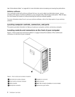
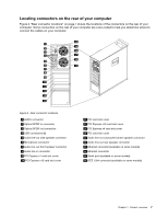
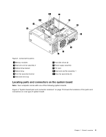
Figure 3. Component locations 1 Memory modules 2 Heat sink and fan assembly 2 3 Optical drive bracket 4 Optical drive 5 Front fan assembly bracket 6 Hard disk drive bay 7 Hard disk drives (3) 8 Power supply assembly 9 PCI card 10 Heat sink and fan assembly 1 11 Rear fan assemblies (2) Locating parts and connectors on the system board Note: Your computer comes with one of the following system boards. Figure 4 "System board part and connector locations" on page 10 shows the locations of the parts and connectors on one type of system board. Chapter 1. Product overview 9
-
 1
1 -
2
-
3
-
4
-
5
-
6
-
7
-
8
-
9
-
 10
10 -
 11
11 -
 12
12 -
 13
13 -
 14
14 -
 15
15 -
 16
16 -
 17
17 -
 18
18 -
 19
19 -
 20
20 -
21
-
22
-
23
-
24
-
25
-
26
-
27
-
28
-
29
-
30
-
31
-
32
-
33
-
34
-
35
-
36
-
37
-
38
-
39
-
40
-
41
-
42
-
43
-
44
-
45
-
46
-
47
-
48
-
49
-
50
-
51
-
52
-
53
-
54
-
55
-
56
-
57
-
58
-
59
-
60
-
61
-
62
-
63
-
64
-
65
-
66
-
67
-
68
-
69
-
70
-
71
-
72
-
73
-
74
-
75
-
76
-
77
-
78
-
79
-
80
-
81
-
82
-
83
-
84
-
85
-
86
-
87
-
88
-
89
-
90
-
91
-
92
 |
 |
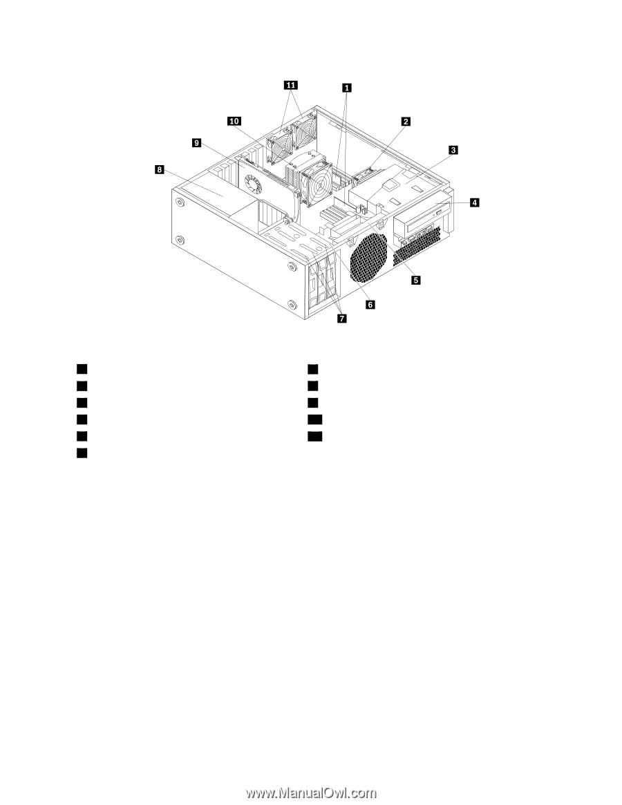
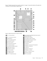
Figure 3. Component locations
1
Memory modules
7
Hard disk drives (3)
2
Heat sink and fan assembly 2
8
Power supply assembly
3
Optical drive bracket
9
PCI card
4
Optical drive
10
Heat sink and fan assembly 1
5
Front fan assembly bracket
11
Rear fan assemblies (2)
6
Hard disk drive bay
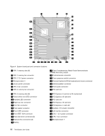
Locating parts and connectors on the system board
Note:
Your computer comes with one of the following system boards.
Figure 4 “System board part and connector locations” on page 10 shows the locations of the parts and
connectors on one type of system board.
Chapter 1
.
Product overview
9