Lenovo ThinkStation C20 (English) User Guide - Page 17
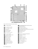
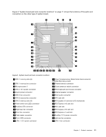
System board part and connector locations on shows the locations of the parts
 |
View all Lenovo ThinkStation C20 manuals
Add to My Manuals
Save this manual to your list of manuals |
Page 17 highlights
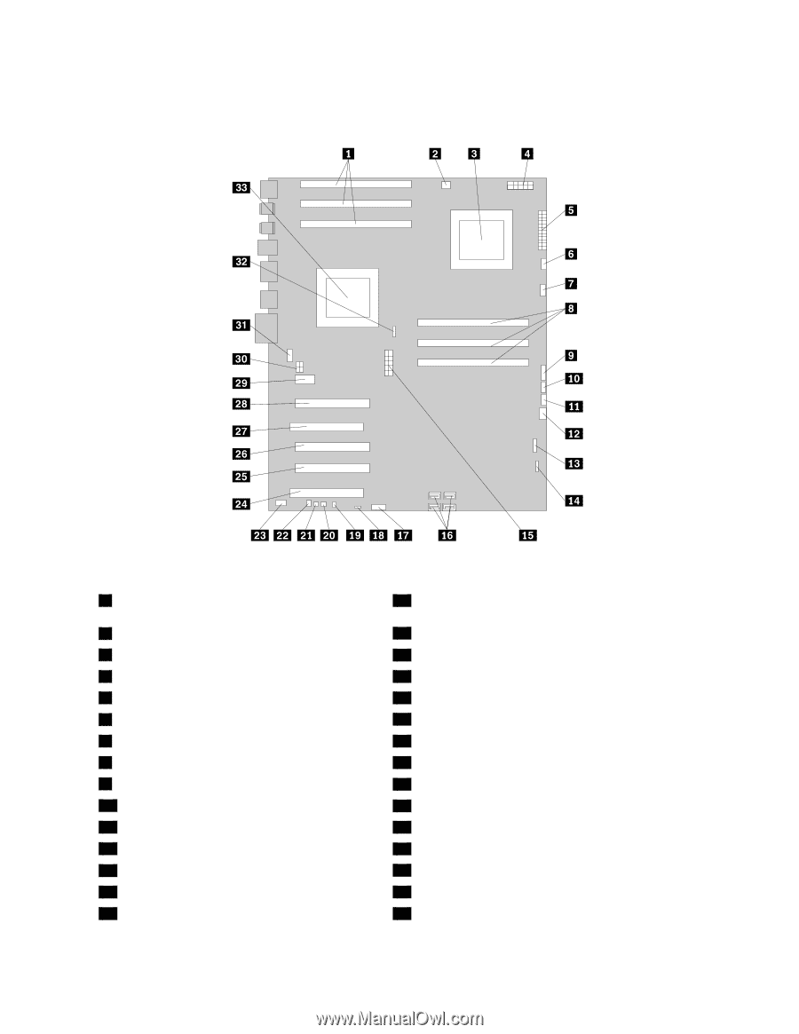
Figure 5 "System board part and connector locations" on page 11 shows the locations of the parts and connectors on the other type of system board. Figure 5. System board part and connector locations 1 CPU 1 memory slots (3) 2 CPU 1 memory fan connector 3 Microprocessor 2 4 CPU 2 12 V power connector 5 24-pin power connector 6 CPU 2 fan connector 7 CPU 2 memory fan connector 8 CPU 2 memory slots (3) 9 Power switch and LEDs connector 10 Auxiliary LED connector 11 Right rear fan connector 12 Front fan connector 13 Card reader connector 14 Front USB connector 15 CPU 1 12 V power connector 18 Clear Complementary Metal Oxide Semiconductor (CMOS) /Recovery jumper 19 Thermal sensor connector 20 Cover presence switch connector 21 PS/2 keyboard and mouse connector 22 Internal speaker connector 23 Front audio connector 24 PCI card slot 25 PCI Express x4 card slot (x16 mechanical) 26 PCI Express x16 card slot 27 PCI card slot 28 PCI Express x16 card slot 29 PCI Express x1 card slot 30 Auxiliary 12 V power connector 31 Left rear fan connector 32 CPU 1 fan connector Chapter 1. Product overview 11
-
 1
1 -
2
-
3
-
4
-
5
-
6
-
7
-
8
-
9
-
10
-
11
-
 12
12 -
 13
13 -
 14
14 -
 15
15 -
 16
16 -
 17
17 -
 18
18 -
 19
19 -
 20
20 -
 21
21 -
 22
22 -
23
-
24
-
25
-
26
-
27
-
28
-
29
-
30
-
31
-
32
-
33
-
34
-
35
-
36
-
37
-
38
-
39
-
40
-
41
-
42
-
43
-
44
-
45
-
46
-
47
-
48
-
49
-
50
-
51
-
52
-
53
-
54
-
55
-
56
-
57
-
58
-
59
-
60
-
61
-
62
-
63
-
64
-
65
-
66
-
67
-
68
-
69
-
70
-
71
-
72
-
73
-
74
-
75
-
76
-
77
-
78
-
79
-
80
-
81
-
82
-
83
-
84
-
85
-
86
-
87
-
88
-
89
-
90
-
91
-
92
 |
 |