LiftMaster LA400DC LA400DC Owner's Manual - Page 10
Overview Of Typical Installation, Dual Gate, Single Gate
 |
View all LiftMaster LA400DC manuals
Add to My Manuals
Save this manual to your list of manuals |
Page 10 highlights
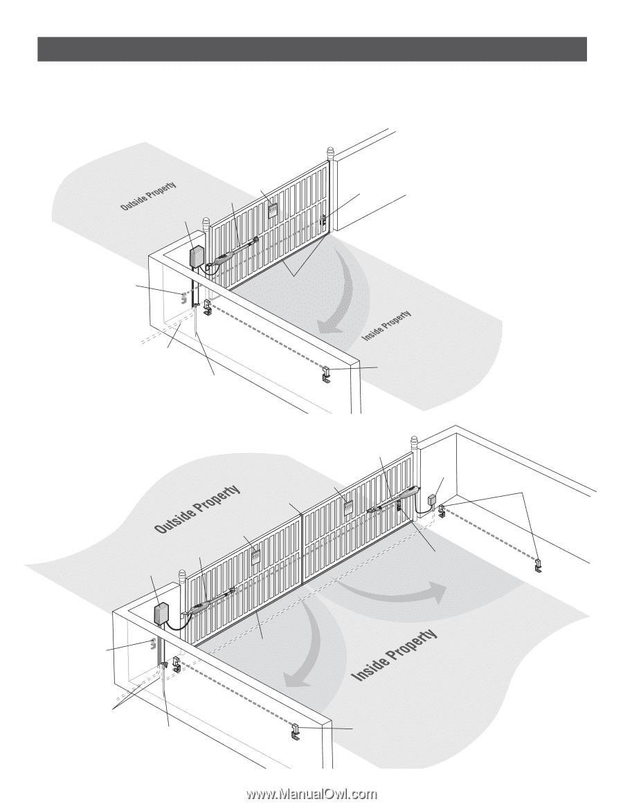
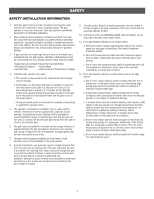
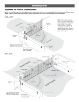
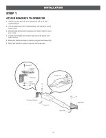
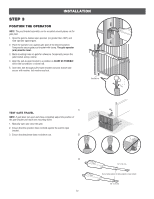
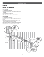
INTRODUCTION OVERVIEW OF TYPICAL INSTALLATION Identify your installation type (refer to the Appendix in the back of the manual for more information). All the illustrations on the following pages display a typical Left-Hand Gate installation with a pull-to-open bracket. For Push-to-Open applications refer to the Appendix. SINGLE GATE Control Box Warning Sign Operator Photoelectric Sensors NOTE: One or more non-contact sensors shall be located where the risk of entrapment or obstruction exists at either the opening or closing direction. Care shall be exercised to reduce the risk of nuisance tripping, such as when a vehicle, trips the sensor while the gate is still moving. Photoelectric Sensors Edge Sensors Water Tight Conduit (Not provided) NOTE: Power and control wiring MUST be run in separate conduits. Earth Ground Rod Check national and local codes for proper depth Photoelectric Sensors DUAL GATE Secondary Operator Warning Sign Edge Sensor Junction Box Photoelectric Sensors Warning Sign Primary Operator Control Box Photoelectric Sensors Photoelectric Sensors Edge Sensor Water Tight Conduit (Not provided) NOTE: Power and control wiring MUST be run in separate conduits. Earth Ground Rod Check national and local codes for proper depth Photoelectric Sensors 8
-
 1
1 -
2
-
3
-
4
-
 5
5 -
 6
6 -
 7
7 -
 8
8 -
 9
9 -
 10
10 -
 11
11 -
 12
12 -
 13
13 -
 14
14 -
 15
15 -
16
-
17
-
18
-
19
-
20
-
21
-
22
-
23
-
24
-
25
-
26
-
27
-
28
-
29
-
30
-
31
-
32
-
33
-
34
-
35
-
36
-
37
-
38
-
39
-
40
-
41
-
42
-
43
-
44
-
45
-
46
-
47
-
48
-
49
-
50
-
51
-
52
-
53
-
54
 |
 |