LiftMaster LA400DC LA400DC Owner's Manual - Page 24
Power Wiring - reviews
 |
View all LiftMaster LA400DC manuals
Add to My Manuals
Save this manual to your list of manuals |
Page 24 highlights
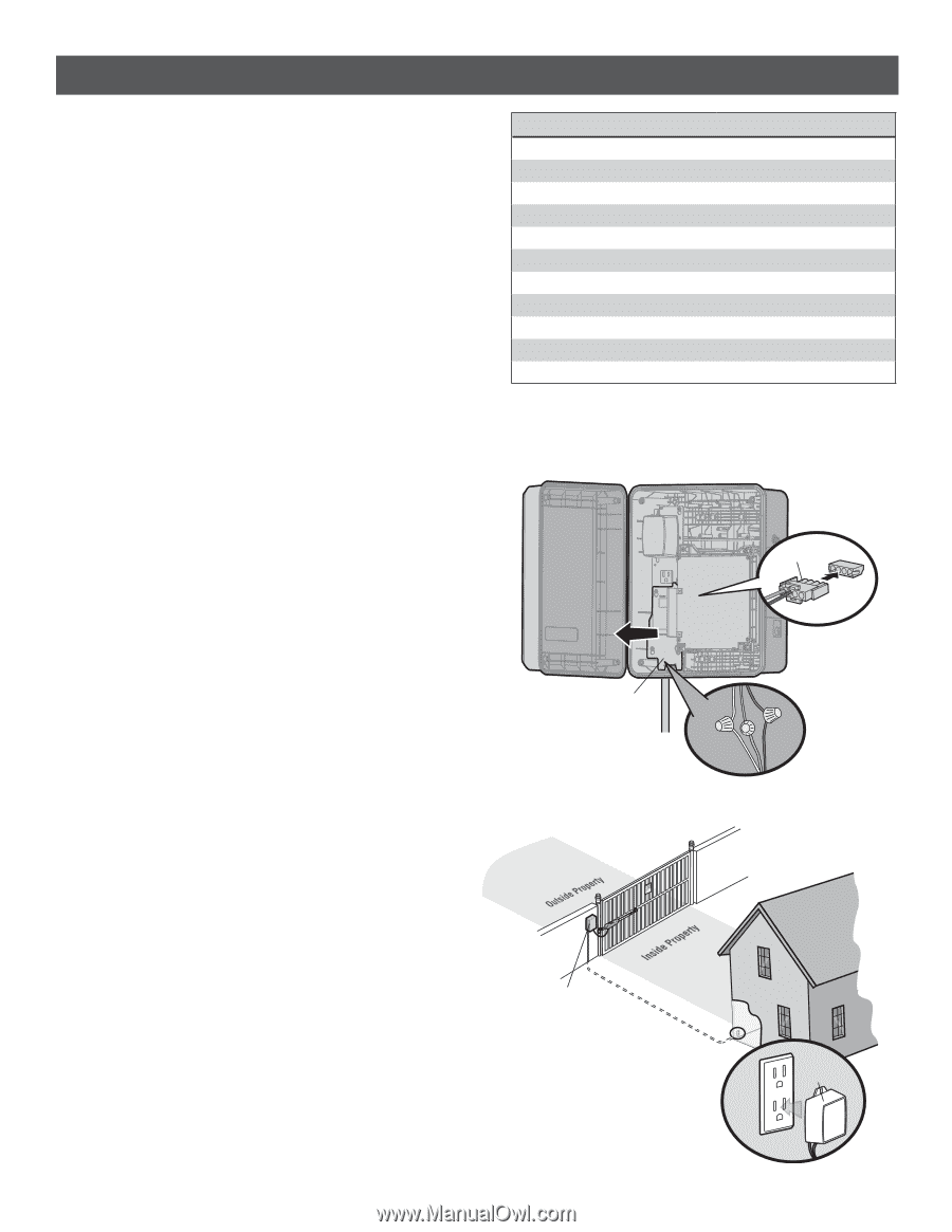
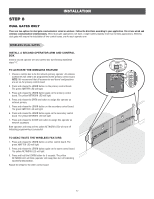
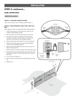
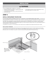
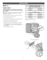
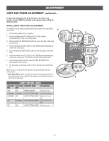
INSTALLATION STEP 10 POWER WIRING SOLAR APPLICATIONS: For solar applications refer to Solar Panels section in the Appendix, pages 42-46. Follow the directions according to your application. NOTE: All power wiring should be on a dedicated circuit, calculated using NEC guidelines. Local codes and conditions must be reviewed for suitability of wire installation. 1. Turn off the AC power from the main power source circuit breaker. 2. Run the AC power wires to the control box. 3. Remove the junction box cover. 4. Connect the green wire to the earth ground rod wire using a wire nut. 5. Connect the white wire to NEUTRAL using a wire nut. 6. Connect the black wire to HOT using a wire nut. 7. Replace the junction box cover. Ensure the wires are not pinched. 8. Plug the J15 plug into the control board. The control board will power up. NOTE: You may see a small spark when plugging the J15 plug into the board. 9. Turn ON AC power to the operator. OPERATOR POWER SOURCE DIRECT PLUG-IN TRANSFORMER (120 VAC) Wire Gauge 14 350 feet (107 m) Wire Gauge 12 525 feet (160 m) Wire Gauge 10 850 feet (259 m) OR EXTERNAL PLUG-IN TRANSFORMER (24 VAC) Wire Gauge 18 150 feet (46 m) Wire Gauge 16 250 feet (76 m) Wire Gauge 14 400 feet (122 m) Wire Gauge 12 600 feet (183 m) Wire Gauge 10 1,000 feet (305 m) NOTE: Use copper conductors ONLY. STANDARD CONTROL BOX J15 Plug Junction Box Cover EXTERNAL PLUG-IN TRANSFORMER Control Box 22 Transformer
-
 1
1 -
2
-
3
-
4
-
5
-
6
-
7
-
8
-
9
-
10
-
11
-
12
-
13
-
14
-
15
-
16
-
17
-
18
-
 19
19 -
 20
20 -
 21
21 -
 22
22 -
 23
23 -
 24
24 -
 25
25 -
 26
26 -
 27
27 -
 28
28 -
 29
29 -
30
-
31
-
32
-
33
-
34
-
35
-
36
-
37
-
38
-
39
-
40
-
41
-
42
-
43
-
44
-
45
-
46
-
47
-
48
-
49
-
50
-
51
-
52
-
53
-
54
 |
 |