LiftMaster LA400DC LA400DC Owner's Manual - Page 44
Solar Panel(s), Solar Usage Guide
 |
View all LiftMaster LA400DC manuals
Add to My Manuals
Save this manual to your list of manuals |
Page 44 highlights
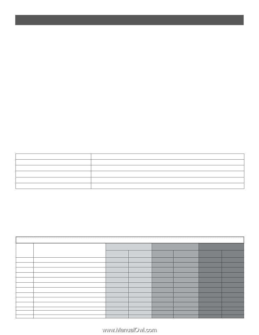
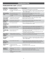
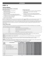
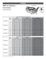
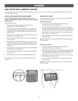
APPENDIX STEP 10 SOLAR PANEL(S) SOLAR PANELS ARE NOT PROVIDED. SEE ACCESSORIES. 33AH Battery Requirements: 7AH Battery Requirements: • Large Metal Control Box for Solar Applications (Model XLSOLARCONTDC) • A minimum of two 10W solar panels in series (Model SOLPNL10W12V) • A maximum of six 10W solar panels (Model SOLPNL10W12V). Configuration of three sets of two 10W paralleled panels put in series. • Two 33AH Batteries (Model A12330SGLPK) • Solar Battery Harness (Model K94-37236) • Standard Control Box for Solar Applications (Model LA400CONTDC) • A minimum of two 10W solar panels in series (Model SOLPNL10W12V) • A maximum of six 10W solar panels (Model SOLPNL10W12V). Configuration of three sets of two 10W paralleled panels put in series. • Two 7AH batteries (29-NP712) • Solar Battery Harness (Model K94-37236) • Battery Tray (Model K10-36183) Disconnect the expansion board if it is not in use to improve performance. We recommend LiftMaster low power draw accessories to minimize power draw, refer to accessory page. Use the tables below to see performance trade-offs. NOTE: Input solar power is 24 Vdc at 60 watts maximum. The solar panel(s) must be located in an open area clear of obstructions and shading for the entire day. The gate operator is not supported in northern climates where temperatures reach below -4˚F. This is due to cold weather and a reduced number of hours of sunlight during the winter months. Cycle rate may vary from solar chart for areas that reach below 32˚F. Solar panels should be cleaned on a regular basis for best performance to ensure proper operation. SOLAR USAGE GUIDE The LA400DC has best in class solar performance due to highly efficient electronics that draw very little power while the gate is not in use (standby). Typical System Standby Battery Current Consumption (mA) System Configuration 2.7 mA Main control board draw with no remote controls programmed +1 mA Low band radio receiver active (one or more wireless transmitters learned) +2.4 mA High band radio active (MyQ device programmed) +11.1 mA +3.8 mA Expansion board Per loop detector (up to 3 loop detectors can be plugged into the expansion board) This low current draw drastically increases the number of days the operator can remain in standby. To determine your system's performance, reference the above table and determine how many milliamps (mA) your system will draw from the batteries. EXAMPLE 1: A system with only a main control board and one or more hand held remote controls programmed will draw 3.7 mA from the batteries while the system is in standby (2.7 mA + 1 mA = 3.7 mA). EXAMPLE 2: A system with only a main control board, one or more hand held remote controls programmed, and 20 mA of external accessories connected to the main control board's accessory power output will draw 23.7 mA from the batteries while the system is in standby (2.7 mA + 1 mA + 20 mA = 23.7 mA). EXAMPLE 3: A system with a main control board, expansion board, two loop detectors, and one or more hand held remote controls programmed will draw 18 mA from the batteries while the system is in standby (2.7 mA + 11.1 mA + 3.8 mA*2 +1 = 18.6 mA). Operator performance with no sun or loss of AC power BATTERY CURRENT DRAW (mA) SYSTEM CONFIGURATION 2.7 main control board only 3.7 remote controls programmed 6.1 remote controls and MyQ programmed 14.8 remote controls and expansion board 18.6 remote controls, expansion board, and one loop detector 26.2 remote controls, expansion board, and three loop detectors 30 40 60 100 200 300 500 All numbers are estimates. Actual results may vary. DAYS OF STANDBY 7AH batteries 33AH batteries 133 180 97 180 59 180 24 105 19 84 14 60 12 52 9 39 6 26 4 16 2 8 1 5 1 3 42 SINGLE GATE CYCLES ON BATTERY 7AH batteries 33AH batteries 400 3623 400 3622 400 3622 400 3621 400 3620 400 3619 400 3619 400 3618 400 3615 400 3610 400 3596 400 3583 400 3557 DUAL GATE CYCLES ON BATTERY 7AH batteries 33AH batteries 330 1752 330 1752 330 1752 330 1752 330 1751 329 1751 329 1751 329 1750 328 1749 326 1746 322 1740 318 1734 311 1721
-
 1
1 -
2
-
3
-
4
-
5
-
6
-
7
-
8
-
9
-
10
-
11
-
12
-
13
-
14
-
15
-
16
-
17
-
18
-
19
-
20
-
21
-
22
-
23
-
24
-
25
-
26
-
27
-
28
-
29
-
30
-
31
-
32
-
33
-
34
-
35
-
36
-
37
-
38
-
 39
39 -
 40
40 -
 41
41 -
 42
42 -
 43
43 -
 44
44 -
 45
45 -
 46
46 -
 47
47 -
 48
48 -
 49
49 -
50
-
51
-
52
-
53
-
54
 |
 |