LiftMaster LA400DC LA400DC Owner's Manual - Page 18
Earth Ground Rod, Wire The Operator Arm To The Control Board, Wire The Operator Arm To
 |
View all LiftMaster LA400DC manuals
Add to My Manuals
Save this manual to your list of manuals |
Page 18 highlights
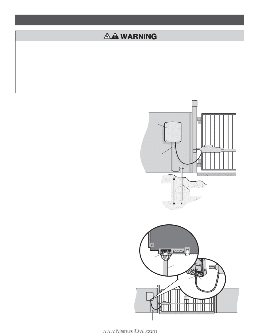
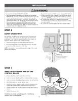
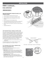
INSTALLATION To reduce the risk of SEVERE INJURY or DEATH: • ANY maintenance to the operator or in the area near the operator MUST NOT be performed until disconnecting the electrical power (AC or solar and battery) and locking-out the power via the operator power switch. Upon completion of maintenance the area MUST be cleared and secured, at that time the unit may be returned to service. • Disconnect power at the fuse box BEFORE proceeding. Operator MUST be properly grounded and connected in accordance with national and local electrical codes. NOTE: The operator should be on a separate fused line of adequate capacity. • ALL electrical connections MUST be made by a qualified individual. • DO NOT install ANY wiring or attempt to run the operator without consulting the wiring diagram. We recommend that you install an edge sensor BEFORE proceeding with the control station installation. • ALL power wiring should be on a dedicated circuit and well protected. The location of the power disconnect should be visible and clearly labeled. • ALL power and control wiring MUST be run in separate conduit. STEP 6 EARTH GROUND ROD Use the proper earth ground rod for your local area. The ground wire must be a single, whole piece of wire. Never splice two wires for the ground wire. If you should cut the ground wire too short, break it, or destroy its integrity, replace it with a single wire length. 1. Install the earth ground rod within 3 feet of the control box. 2. Run wire from the earth ground rod to the control box. The earth ground wire will be connected in a later step. NOTE: If the operator is not grounded properly the range of the remote controls will be reduced. Control Box 12 Gauge Wire Check national and local codes for proper depth Earth Ground Rod (Within 3' (0.9 m) of control box) STEP 7 WIRE THE OPERATOR ARM TO THE CONTROL BOARD 1. Choose a knockout in the bottom of the control box. 2. Insert the operator cable through the provided watertight connector. 3. Insert the operator cable and watertight connector into the knockout. 4. Slide the connector nut onto the operator cable. 5. Connect the operator cable wires to the connector according to the colored label on the connector (white to white, red to red, etc.). 6 Plug the connector into the GATE 1 terminal on the control board as shown. 7. Tighten the connector nut. If installing one operator, proceed to page 19. If installing two operators, go to the following page. 16 (control board) GATE 1 GATE 2 Connector Operator Cable Watertight Connector Connector Nut
-
 1
1 -
2
-
3
-
4
-
5
-
6
-
7
-
8
-
9
-
10
-
11
-
12
-
 13
13 -
 14
14 -
 15
15 -
 16
16 -
 17
17 -
 18
18 -
 19
19 -
 20
20 -
 21
21 -
 22
22 -
 23
23 -
24
-
25
-
26
-
27
-
28
-
29
-
30
-
31
-
32
-
33
-
34
-
35
-
36
-
37
-
38
-
39
-
40
-
41
-
42
-
43
-
44
-
45
-
46
-
47
-
48
-
49
-
50
-
51
-
52
-
53
-
54
 |
 |