LiftMaster LA400DC LA400DC Owner's Manual - Page 25
Finish Install, Adjustment, Limit And Force Adjustment, Installation - motor
 |
View all LiftMaster LA400DC manuals
Add to My Manuals
Save this manual to your list of manuals |
Page 25 highlights
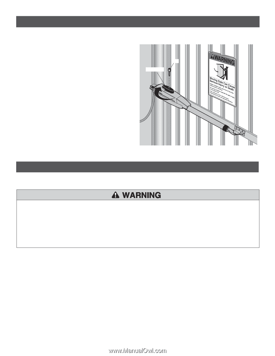
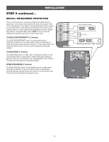
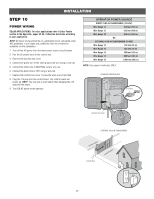
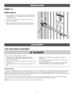
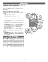
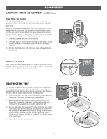
INSTALLATION STEP 11 FINISH INSTALL 1. Turn the release lever clockwise 180° back to the engaged position. This engages the motor. The illustration shows the release lever in the engaged position. 2. Turn the key clockwise 180°. This locks the release lever. The operator is now engaged. 3. Fasten warning signs to the gate with cable ties. Warning signs MUST be installed on both sides of the gate and in plain view. Key Release Lever ADJUSTMENT LIMIT AND FORCE ADJUSTMENT To reduce the risk of SEVERE INJURY or DEATH: • Without a properly installed safety reversal system, persons (particularly small children) could be SERIOUSLY INJURED or KILLED by a moving gate. • Too much force on gate will interfere with proper operation of safety reversal system. • NEVER increase force beyond minimum amount required to move gate. • NEVER use force adjustments to compensate for a binding or sticking gate. • If one control (force or travel limits) is adjusted, the other control may also need adjustment. • After ANY adjustments are made, the safety reversal system MUST be tested. Gate MUST reverse on contact with a rigid object. INTRODUCTION Your operator is designed with electronic controls to make travel limit and force adjustments easy. The adjustments allow you to program where the gate will stop in the open and close position. The electronic controls sense the amount of force required to open and close the gate. The force is adjusted automatically when you program the limits but should be fine tuned using the REVERSAL FORCE dial on the control board (refer to Fine Tune the Force section) to compensate for environmental changes. The limits can be set using the control board (following page) or a remote control (refer to Limit Setup with a Remote Control in the Appendix). Setting the limits with a remote control requires a 3-button remote control programmed to OPEN, CLOSE, and STOP. NOTE: The Test Buttons on the control board will not work until the limits have been set. 23
-
 1
1 -
2
-
3
-
4
-
5
-
6
-
7
-
8
-
9
-
10
-
11
-
12
-
13
-
14
-
15
-
16
-
17
-
18
-
19
-
 20
20 -
 21
21 -
 22
22 -
 23
23 -
 24
24 -
 25
25 -
 26
26 -
 27
27 -
 28
28 -
 29
29 -
 30
30 -
31
-
32
-
33
-
34
-
35
-
36
-
37
-
38
-
39
-
40
-
41
-
42
-
43
-
44
-
45
-
46
-
47
-
48
-
49
-
50
-
51
-
52
-
53
-
54
 |
 |