LiftMaster LA400DC LA400DC Owner's Manual - Page 21
Wired Dual Gates, Wire The Secondary Operator Arm To The, Control Board
 |
View all LiftMaster LA400DC manuals
Add to My Manuals
Save this manual to your list of manuals |
Page 21 highlights
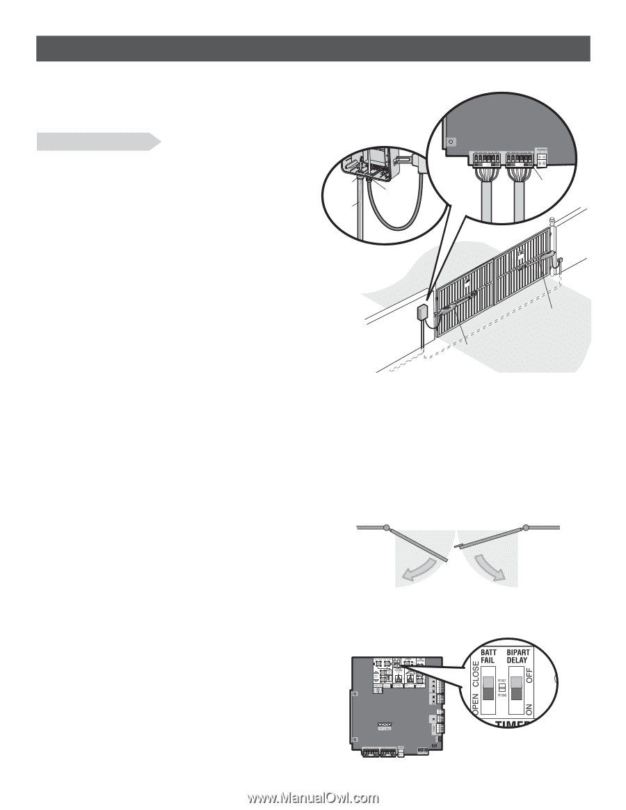
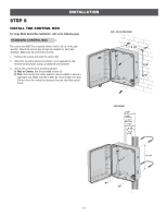
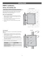
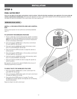
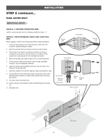
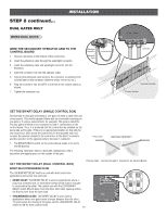
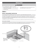
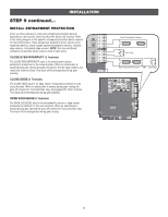
STEP 8 continued... DUAL GATES ONLY WIRED DUAL GATES INSTALLATION WIRE THE SECONDARY OPERATOR ARM TO THE CONTROL BOARD 1. Choose a knockout in the bottom of the control box. 2. Insert the extension cable through the watertight connector. 3. Insert the extension cable and watertight connector into the knockout. 4. Slide the connector nut onto the operator cable. 5. Connect the extension cable wires to the connector according to the colored label on the connector (white to white, red to red, etc.). 6. Plug the connector into the GATE 2 terminal on the control board as shown. 7. Tighten the connector nut. Watertight Connector Extension Cable Connector Nut GATE 1 GATE 2 (Control Board) Connector KtDPpTiMmlheEoadiEyseneoPoieswntnvtCirtttliLiehhrIaanEteonnncAusggjchtRaumeiplt!GdeirurGsriysoaeaaftrrnoteteuorwaoesmv.rapeereaChnsDryeiiacnaptmelgeean.aosrtahvottCeeehnaglaeytanuattenrsayonerce PTpDtKiMhlmeEoadiEyseneoPioeswnnvttCirtttliLihIerhanantEeonncAusggjchtuRameiptl!dGeriursGriysaoeaaftrronteouetrwaosemv.rapeereahDsnCryeiiacnpatmelgeean.aosrtahvtoteeCenhagleaytantauternasyonrece Secondary Operator Primary Operator SET THE BIPART DELAY (SINGLE CONTROL BOX) Occasionally in dual gate installations, one gate will need to open first and close second. This would happen if there was an ornamental overhang on one gate or if using a solenoid lock, for example. This gate is called the Primary gate and needs to be connected to Gate 1 connections on the control board. Thus, it is preferred that the control box be installed on the same side as this gate. If there is no appropriate location on that side for the control box, then mount the control box on the opposite side, but connect the operator closest to the control box to the Gate 2 connector and the operator on the opposite side to the Gate 1 connector. 1. The BIPART DELAY switch on the control board needs to be set to the ON position. The following illustration shows a dual gate configuration with a decorative overlapping piece on the outside of the gate. Primary Gate OUTSIDE PROPERTY SET THE BIPART DELAY (DUAL CONTROL BOX) Primary Gate - Connect to Gate 1 Connector on Control Board. BIPART DELAY/SYNCHRONIZED CLOSE The LOCK/BIPART DELAY switch is used with dual control box applications and serves two functions: • BIPART DELAY: The BIPART DELAY is used in applications where a mag-lock, solenoid lock, or decorative overlay would require one gate to close before the other. The control box with the LOCK/BIPART DELAY switch ON will delay from the close limit when opening and be the first to close from the open limit. • SYNCHRONIZED CLOSE: The BIPART DELAY is also used in applications where one gate travels a longer distance than the other. To synchronize the closing of the gates, set the LOCK/BIPART DELAY switch to ON for both control boxes. 19
-
 1
1 -
2
-
3
-
4
-
5
-
6
-
7
-
8
-
9
-
10
-
11
-
12
-
13
-
14
-
15
-
 16
16 -
 17
17 -
 18
18 -
 19
19 -
 20
20 -
 21
21 -
 22
22 -
 23
23 -
 24
24 -
 25
25 -
 26
26 -
27
-
28
-
29
-
30
-
31
-
32
-
33
-
34
-
35
-
36
-
37
-
38
-
39
-
40
-
41
-
42
-
43
-
44
-
45
-
46
-
47
-
48
-
49
-
50
-
51
-
52
-
53
-
54
 |
 |