LiftMaster LA500 LA500 Manual - Page 18
Standard Control Box, Mount The Control Box
 |
View all LiftMaster LA500 manuals
Add to My Manuals
Save this manual to your list of manuals |
Page 18 highlights
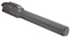
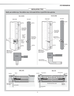
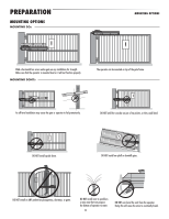
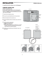
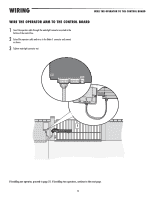
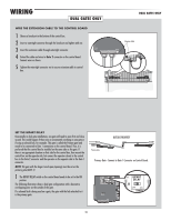
INSTALLATION For Large Metal Control Box installation, refer to the following page. STANDARD CONTROL BOX MOUNT THE CONTROL BOX The control box MUST be mounted within 5 feet (1.52 m) of the gate operator. Mount the control box as high as possible for best radio reception. Make sure the control box is level. NOTE: The expansion board DOES NOT need to be removed for a wall or column mount installation. 1 Remove the screws and open the control box. 2 Disconnect the connector labeled "Main Board" on the expansion board. 3 Remove the expansion board by removing the screws. 4 Select the mounting holes and remove the knockouts using a screwdriver and hammer. 5 Secure the control box to mounting surface. A. Column: Use the provided screws (4). B. Wall: Use the provided screws (4). C. Post: Use U-bolts and rubber washers (not provided) to ensure a watertight seal. Make sure the U-bolts do not protrude more than 3/4 inch from the control box because this can short the control board. 6 Reinstall the expansion board and connect the "Main Board" connector to the expansion board. STANDARD CONTROL BOX Expansion Board "Main Board" Connector WALL OR COLUMN MOUNT 9.13" POST MOUNT 6.36" 4.38" 3.88" 5.88" 4.88" 2.88" 13.75" 12.06" A B C 16
-
 1
1 -
2
-
3
-
4
-
5
-
6
-
7
-
8
-
9
-
10
-
11
-
12
-
 13
13 -
 14
14 -
 15
15 -
 16
16 -
 17
17 -
 18
18 -
 19
19 -
 20
20 -
 21
21 -
 22
22 -
 23
23 -
24
-
25
-
26
-
27
-
28
-
29
-
30
-
31
-
32
-
33
-
34
-
35
-
36
-
37
-
38
-
39
-
40
-
41
-
42
-
43
-
44
-
45
-
46
-
47
-
48
 |
 |