1
When you see these Safety Symbols and Signal Words on the following pages, they
will alert you to the possibility of serious injury or death if you do not comply with
the warnings that accompany them. The hazard may come from something
mechanical or from electric shock. Read the warnings carefully.
When you see this Signal Word on the following pages, it will alert you to the
possibility of damage to your gate and/or the gate operator if you do not comply
with the cautionary statements that accompany it. Read them carefully.
IMPORTANT NOTE
•
BEFORE attempting to install, operate or maintain the operator, you must read
and fully understand this manual and follow all safety instructions.
•
DO NOT attempt repair or service of your gate operator unless you are an
Authorized Service Technician.
MECHANICAL
ELECTRICAL
SAFETY
1-7
Safety Symbol and Signal Word Review . . . . . . . . . . . . . . . . . . . . . . . . . . . . . . . 1
UL325 Model Classifications . . . . . . . . . . . . . . . . . . . . . . . . . . . . . . . . . . . . . . . . 2
Safety Installation Information. . . . . . . . . . . . . . . . . . . . . . . . . . . . . . . . . . . . . . 3
Gate Construction Information . . . . . . . . . . . . . . . . . . . . . . . . . . . . . . . . . . . . . . 4
Required Entrapment Protection Devices. . . . . . . . . . . . . . . . . . . . . . . . . . . . . . . 5
Important Safety Information . . . . . . . . . . . . . . . . . . . . . . . . . . . . . . . . . . . . .6-7
INTRODUCTION
8-9
Operator Specifications . . . . . . . . . . . . . . . . . . . . . . . . . . . . . . . . . . . . . . . . . . . 8
Carton Inventory & Operator Dimensions . . . . . . . . . . . . . . . . . . . . . . . . . . . . . . 8
Features . . . . . . . . . . . . . . . . . . . . . . . . . . . . . . . . . . . . . . . . . . . . . . . . . . . . . . 9
PREPARATION
10-12
Site Preparation . . . . . . . . . . . . . . . . . . . . . . . . . . . . . . . . . . . . . . . . . . . . .10-11
Mounting Options . . . . . . . . . . . . . . . . . . . . . . . . . . . . . . . . . . . . . . . . . . . . . . 12
INSTALLATION
13-17
Manual Release . . . . . . . . . . . . . . . . . . . . . . . . . . . . . . . . . . . . . . . . . . . . . . . . 13
Determine the Position of the Post Bracket . . . . . . . . . . . . . . . . . . . . . . . . . . . . 13
Determine the Position of the Gate Bracket . . . . . . . . . . . . . . . . . . . . . . . . . . . 14
Weld the Brackets . . . . . . . . . . . . . . . . . . . . . . . . . . . . . . . . . . . . . . . . . . . . . . 14
Attach the Operator to the Brackets . . . . . . . . . . . . . . . . . . . . . . . . . . . . . . . . . 15
Standard Control Box. . . . . . . . . . . . . . . . . . . . . . . . . . . . . . . . . . . . . . . . . . . . 16
Large Metal Control Box (XLM) . . . . . . . . . . . . . . . . . . . . . . . . . . . . . . . . . . . . 17
WIRING
18-24
Wire the Entrapment Protection Devices . . . . . . . . . . . . . . . . . . . . . . . . . . . . . . 18
Earth Ground Rod . . . . . . . . . . . . . . . . . . . . . . . . . . . . . . . . . . . . . . . . . . . . . . 18
Wire the Operator Arm to the Control Board. . . . . . . . . . . . . . . . . . . . . . . . . . . 19
Dual Gates Only . . . . . . . . . . . . . . . . . . . . . . . . . . . . . . . . . . . . . . . . . . . . .20-21
Power Wiring. . . . . . . . . . . . . . . . . . . . . . . . . . . . . . . . . . . . . . . . . . . . . . . .22-23
Connect Batteries . . . . . . . . . . . . . . . . . . . . . . . . . . . . . . . . . . . . . . . . . . . . .23-24
Engage the Operator . . . . . . . . . . . . . . . . . . . . . . . . . . . . . . . . . . . . . . . . . . . . 24
ADJUSTMENT
25-26
Limit and Force Adjustment . . . . . . . . . . . . . . . . . . . . . . . . . . . . . . . . . . . . .25-26
Obstruction Test . . . . . . . . . . . . . . . . . . . . . . . . . . . . . . . . . . . . . . . . . . . . . . . . 26
PROGRAMMING
27-28
Remote Controls . . . . . . . . . . . . . . . . . . . . . . . . . . . . . . . . . . . . . . . . . . . . . . . 27
Erase All Codes
. . . . . . . . . . . . . . . . . . . . . . . . . . . . . . . . . . . . . . . . . . . . . . . . 27
OPERATION
28
Manual Release . . . . . . . . . . . . . . . . . . . . . . . . . . . . . . . . . . . . . . . . . . . . . . . . 28
Reset Button . . . . . . . . . . . . . . . . . . . . . . . . . . . . . . . . . . . . . . . . . . . . . . . . . . 28
Remote Control . . . . . . . . . . . . . . . . . . . . . . . . . . . . . . . . . . . . . . . . . . . . . . . . 28
Party Mode . . . . . . . . . . . . . . . . . . . . . . . . . . . . . . . . . . . . . . . . . . . . . . . . . . . 28
MAINTENANCE
29
Maintenance Chart. . . . . . . . . . . . . . . . . . . . . . . . . . . . . . . . . . . . . . . . . . . . . . 29
Batteries . . . . . . . . . . . . . . . . . . . . . . . . . . . . . . . . . . . . . . . . . . . . . . . . . . . . . 29
ADDITIONAL FEATURES
29-35
LiftMaster Internet Gateway. . . . . . . . . . . . . . . . . . . . . . . . . . . . . . . . . . . . . . . 29
Control Board Overview . . . . . . . . . . . . . . . . . . . . . . . . . . . . . . . . . . . . . . . . . . 30
Accessory Features on Control Board . . . . . . . . . . . . . . . . . . . . . . . . . . . . . . . . 31
Expansion Board Overview . . . . . . . . . . . . . . . . . . . . . . . . . . . . . . . . . . . . . . . 32
Accessory Features on Expansion Board . . . . . . . . . . . . . . . . . . . . . . . . . . . . . . 33
Gate Operator Setup Examples . . . . . . . . . . . . . . . . . . . . . . . . . . . . . . . . . . . . 34
Limit Setup with a Remote Control . . . . . . . . . . . . . . . . . . . . . . . . . . . . . . . . . . 35
TROUBLESHOOTING
36-41
Control Board LEDs . . . . . . . . . . . . . . . . . . . . . . . . . . . . . . . . . . . . . . . . . . .36-37
Troubleshooting Chart . . . . . . . . . . . . . . . . . . . . . . . . . . . . . . . . . . . . . . . . .38-41
WIRING DIAGRAMS
42-43
Standard Control Box. . . . . . . . . . . . . . . . . . . . . . . . . . . . . . . . . . . . . . . . . . . . 42
Large Metal Control Box (XLM) . . . . . . . . . . . . . . . . . . . . . . . . . . . . . . . . . . . . 43
ACCESSORIES
44
REPAIR PARTS
45
WARRANTY
46
TABLE OF CONTENTS
SAFETY SYMBOL AND SIGNAL WORD REVIEW
SAFETY
 1
1 2
2 3
3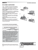 4
4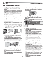 5
5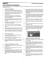 6
6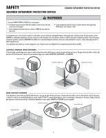 7
7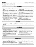 8
8 9
9