LiftMaster LA500 LA500 Manual - Page 20
Wiring, Wire The Entrapment Protection Devices, Earth Ground Rod - remote
 |
View all LiftMaster LA500 manuals
Add to My Manuals
Save this manual to your list of manuals |
Page 20 highlights
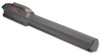
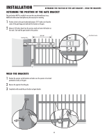
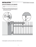
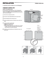
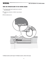
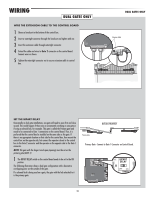
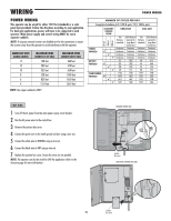
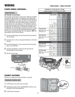
WIRING WIRE THE ENTRAPMENT PROTECTION DEVICES + EARTH GROUND ROD WIRE THE ENTRAPMENT PROTECTION DEVICES Entrapment protection devices are required. Refer to page 5 for more information regarding application. To prevent SERIOUS INJURY or DEATH from a moving gate: • Entrapment protection devices MUST be installed to protect anyone who may come near a moving gate. • Locate entrapment protection devices to protect in BOTH the open and close gate cycles. • Locate entrapment protection devices to protect between moving gate and RIGID objects, such as posts or walls. 1 Connect the entrapment protection device to the EYES EDGE terminal on the control board. These inputs are for pulsed photoelectric sensors and dry contact edges. • Close Photoelectric Sensor Entrapment Protection: Connect wires from the photoelectric sensors to the Inputs on the CLOSE EYES/INTERRUPT terminal. • Close Edge Entrapment Protection: Connect wires from the entrapment protection device to the Inputs on the CLOSE EDGE terminal. • Open Entrapment Protection: Connect wires from the entrapment protection device to the Inputs on the OPEN EYES/EDGE terminal. NOTE: Refer to the "Accessory Features on the Control Board" section on page 31. TO ERASE LEARNED MONITORED PHOTOELECTRIC SENSORS 1 Remove the photoelectric sensor wires from the terminal block. 2 Press and release the SET OPEN and SET CLOSE buttons simultaneously. The SET OPEN and SET CLOSE LEDs will turn on. 3 Press and release both SET OPEN and SET CLOSE buttons again to turn off the SET OPEN and SET CLOSE LEDs. +- SHADOW CLOSE EYES/ INTERRUPT -+ SET PEN SET CL SE CL SE ST P ME GATE FF N RESS & REL ASE TO BEG N LMT ETUP 1 25 E NS 10 60 STATUS: INPUT POWER ATT CHARGING FF T MER 180 M N MX ATT LOW ATE MO ING ACC PWR O L AGNOSTIC CO ES "FIRE EPT " OPEN XIT SHADOW CLOSE EYES/ NTERRUPT +- -+ J5 N C. J15 + BATT - + DC POWER BR GRN WT YE BLU RED BR GRN WT YE BLU RED SOLAR / CHARGER + LOCK LA S 2 U P Y 4V L S GROUND ID RESET ALARM ACCESSORY POWER + ON- + SW-. N.O. EXP. BOAR EARTH GROUND ROD Use the proper earth ground rod for your local area. The ground wire must be a single, whole piece of wire. Never splice two wires for the ground wire. If you should cut the ground wire too short, break it, or destroy its integrity, replace it with a single wire length. 1 Install the earth ground rod within 3 feet of the control box. 2 Run wire from the earth ground rod to the control box. NOTE: If the operator is not grounded properly the range of the remote controls will be reduced. 18 To Control Box Check national and local codes for proper depth
-
 1
1 -
2
-
3
-
4
-
5
-
6
-
7
-
8
-
9
-
10
-
11
-
12
-
13
-
14
-
 15
15 -
 16
16 -
 17
17 -
 18
18 -
 19
19 -
 20
20 -
 21
21 -
 22
22 -
 23
23 -
 24
24 -
 25
25 -
26
-
27
-
28
-
29
-
30
-
31
-
32
-
33
-
34
-
35
-
36
-
37
-
38
-
39
-
40
-
41
-
42
-
43
-
44
-
45
-
46
-
47
-
48
 |
 |