LiftMaster LA500 LA500 Manual - Page 23
Wiring, Bipart, Delay, Timer - dual gate operator
 |
View all LiftMaster LA500 manuals
Add to My Manuals
Save this manual to your list of manuals |
Page 23 highlights
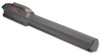
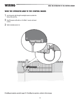
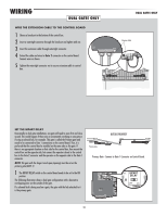
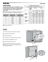
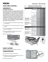
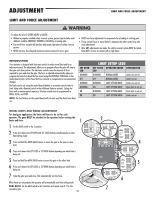
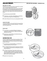
WIRING DUAL GATES ONLY DUAL GATES ONLY WIRE THE EXTENSION CABLE TO THE CONTROL BOARD 1 Choose a knockout in the bottom of the control box. 2 Insert a watertight connector through the knockout and tighten with nut. 3 Insert the extension cable through watertight connector. 4 Extend the cable and wires to Gate 2 connector on the control board. Connect wires as shown. 5 Tighten the watertight connector nut to secure extension cable to control box. GATE 1 GATE 2 Extension Cable BRO GRN WHT YEL BLU RED BRO GRN WHT YEL BLU RED SO AR / CHARGER + ! ! SET THE BIPART DELAY Occasionally in dual gate installations, one gate will need to open first and close second. This would happen if there was an ornamental overhang on one gate or if using a solenoid lock, for example. This gate is called the Primary gate and needs to be connected to Gate 1 connections on the control board. Thus, it is preferred that the control box be installed on the same side as this gate. If there is no appropriate location on that side for the control box, then mount the control box on the opposite side, but connect the operator closest to the control box to the Gate 2 connector and the operator on the opposite side to the Gate 1 connector. NOTE: The gate with the longer travel span (opening) must be set as the primary gate (GATE 1). 1 The BIPART DELAY switch on the control board needs to be set to the ON position. The following illustration shows a dual gate configuration with a decorative overlapping piece on the outside of the gate. If a solenoid lock is being used on a gate, the gate with the lock attached to it is the primary gate. OUTSIDE PROPERTY Primary Gate Primary Gate - Connect to Gate 1 Connector on Control Board. S T OPEN SET CLOSE OFF O XM T ER OK MOVE GATE E E SE O E IN LMT 0 2 5 60 E STOP TATUS OF 80 I PUT POW R T MER A T CHA GI G GA E MOV NG N ATT OW CC PWR OV D D AGNO T C ODES HAD LO E E NT RRU T + J 5 J15 L + B TT + DC P WER POWER A CES ORY BR GRN WT YE BLU R D R G N T YE B U RED SO AR / CH RGER GRO ND D ES T A ARM O N + +W NO M NC + EXP OSE BIPART DELAY OFF ON TIMER 21
-
 1
1 -
2
-
3
-
4
-
5
-
6
-
7
-
8
-
9
-
10
-
11
-
12
-
13
-
14
-
15
-
16
-
17
-
 18
18 -
 19
19 -
 20
20 -
 21
21 -
 22
22 -
 23
23 -
 24
24 -
 25
25 -
 26
26 -
 27
27 -
 28
28 -
29
-
30
-
31
-
32
-
33
-
34
-
35
-
36
-
37
-
38
-
39
-
40
-
41
-
42
-
43
-
44
-
45
-
46
-
47
-
48
 |
 |