LiftMaster LA500 LA500 Manual - Page 25
Connect Batteries - la 500 gate opener
 |
View all LiftMaster LA500 manuals
Add to My Manuals
Save this manual to your list of manuals |
Page 25 highlights
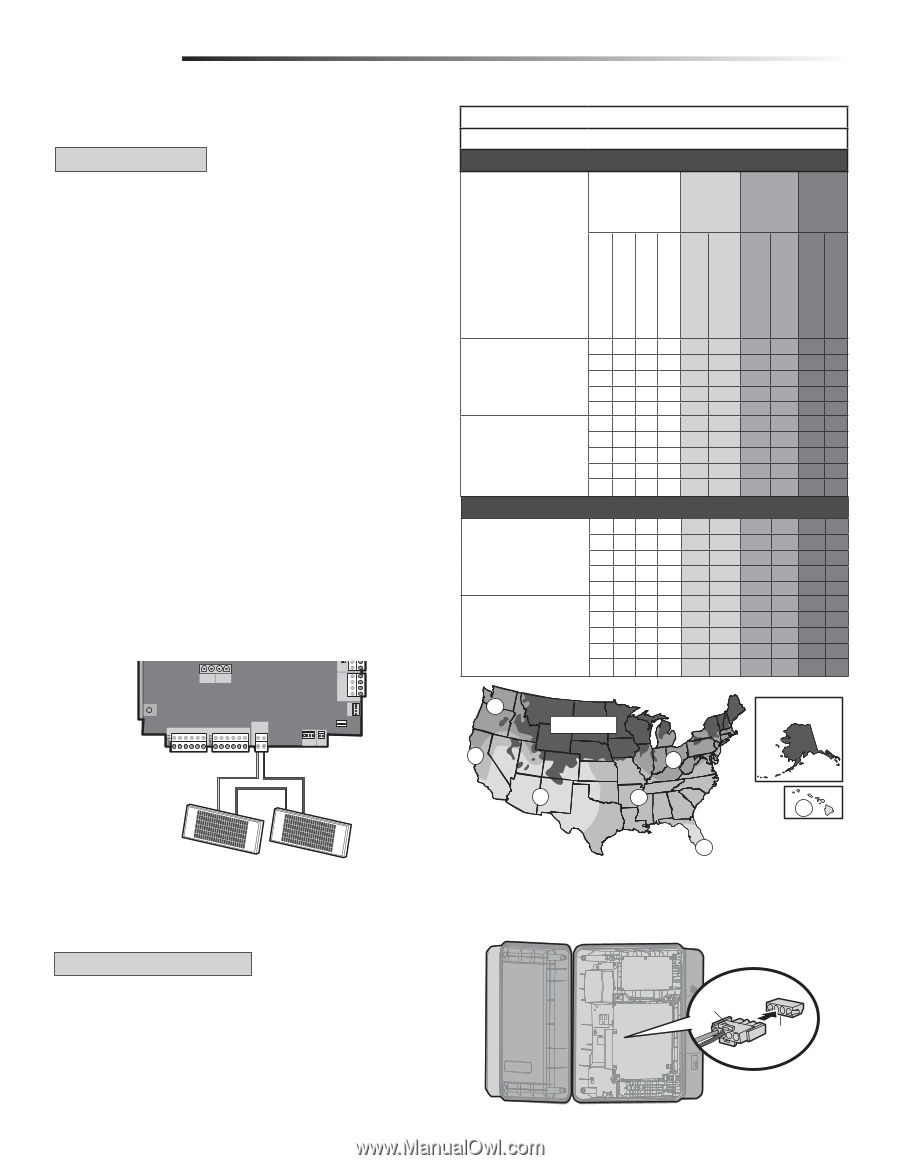
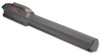
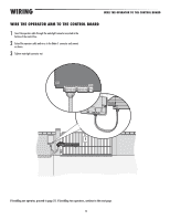
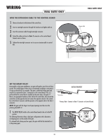
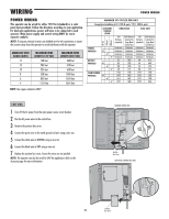
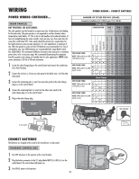
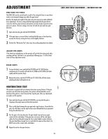
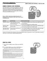
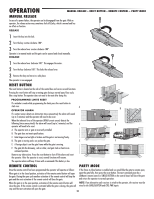
WIRING POWER WIRING CONTINUED... SOLAR PANEL(S) NOT PROVIDED. SEE ACCESSORIES. The solar panel(s) must be located in an open area clear of obstructions and shading for the entire day. The gate operator is not supported in northern climates where temperatures reach below -4˚F. This is due to cold weather and a reduced number of hours of sunlight during the winter months. Cycle rate may vary from solar chart for areas that reach below 32˚F. Solar panels should be cleaned on a regular basis for best performance to ensure proper operation. For solar applications, a minimum of two 10W solar panels in series and two 7AH batteries are recommended. For Zone 3 cold weather sites, two 33AH batteries are recommended (for Large Metal Control Box (XLM) ONLY). We recommend LiftMaster low power draw accessories to minimize power draw, refer to accessory page. We recommend disconnecting the expansion board for greater cycle ratings and standby time for solar applications. NOTE: Solar power maximum is 24 Vdc at 50 watts maximum. 1 Locate the solar/charge plug on the control board and remove the transformer wires from the plug. 2 Connect the red wire (+) from one solar panel to the black wire (-) of the other solar panel. 3 Connect the remaining red (+) wire from one solar panel to the solar/charge plug (+) on the control board. 4 Connect the remaining black (-) wire from the other solar panel to the solar/charge plug (-) on the control board. 5 Plug in the solar/charge plug. N.O. COM J15 + BATT - + DC POWER LOCK ACCESSORY POWER + ON- + SW-. CLASS 2 SUPPLY 24 VOLTS EXP. BOARD BR GRN WT YE BLU RED BR GRN WT YE BLU RED SOLAR / CHARGER + - GROUND ID RESET ALARM Red Black (to solar panels) + - + - POWER WIRING + CONNECT BATTERIES NUMBER OF CYCLES PER DAY (SOLAR) Swing Gate Installation (6 ft. 1200 lb. gate/19 ft. 500 lb.) Single Gate CONFIGURATION ZONE 1 (6 Hrs sunlight/day) ZONE 2 (4 Hrs Sunlight/day) ZONE 3 (2 Hrs Sunlight/ day) Low Band High Band Expansion Board 1 Loop (LD7LP) 7AH Batteries (standard) 33AH Batteries (optional) 7AH Batteries (standard) 33AH Batteries (optional) 7AH Batteries (standard) 33AH Batteries (optional) 20W SOLAR PANEL NOTE: 20W would be two 10W (12V) panels in series. ✔ ✔ ✔ ✔ ✔ 120 154 76 96 33 38 117 151 74 93 30 35 111 144 68 87 25 29 109 142 66 84 23 27 99 131 56 74 13 17 40W SOLAR PANEL NOTE: 40W would be two 20W panels in series. ✔ ✔ ✔ ✔ ✔ 156 202 101 128 45 54 154 199 98 125 42 51 148 193 92 119 37 45 145 190 90 117 35 43 135 179 80 106 25 33 Dual Gates 20W SOLAR PANEL NOTE: 20W would be two 10W (12V) panels in series. ✔ ✔ ✔ ✔ ✔ 54 69 34 43 15 17 53 68 33 42 13 16 50 65 31 39 11 13 49 64 30 38 10 12 45 60 25 33 6 7 40W SOLAR PANEL NOTE: 40W would be two 20W panels in series. ✔ ✔ ✔ ✔ ✔ 71 92 46 58 20 24 70 90 44 57 19 23 67 87 42 54 16 20 66 86 41 53 16 19 62 81 36 48 11 15 3 2 NOT AVAILABLE 3 1 2 NOT AVAILABLE 1 1 CONNECT BATTERIES The batteries are charged in the circuit by the transformer or solar panel. STANDARD CONTROL BOX 1 Turn OFF AC power to the operator at the circuit breaker. 2 Plug the battery connector to the J15 plug labeled BATT(-)(+) DC(-)(+) on the control board. The control board will power up. 3 Turn ON AC power to the operator. 23 Battery Connector J15 Plug
-
 1
1 -
2
-
3
-
4
-
5
-
6
-
7
-
8
-
9
-
10
-
11
-
12
-
13
-
14
-
15
-
16
-
17
-
18
-
19
-
 20
20 -
 21
21 -
 22
22 -
 23
23 -
 24
24 -
 25
25 -
 26
26 -
 27
27 -
 28
28 -
 29
29 -
 30
30 -
31
-
32
-
33
-
34
-
35
-
36
-
37
-
38
-
39
-
40
-
41
-
42
-
43
-
44
-
45
-
46
-
47
-
48
 |
 |