LiftMaster LA500 LA500 Manual - Page 32
Control Board Overview - troubleshooting
 |
View all LiftMaster LA500 manuals
Add to My Manuals
Save this manual to your list of manuals |
Page 32 highlights
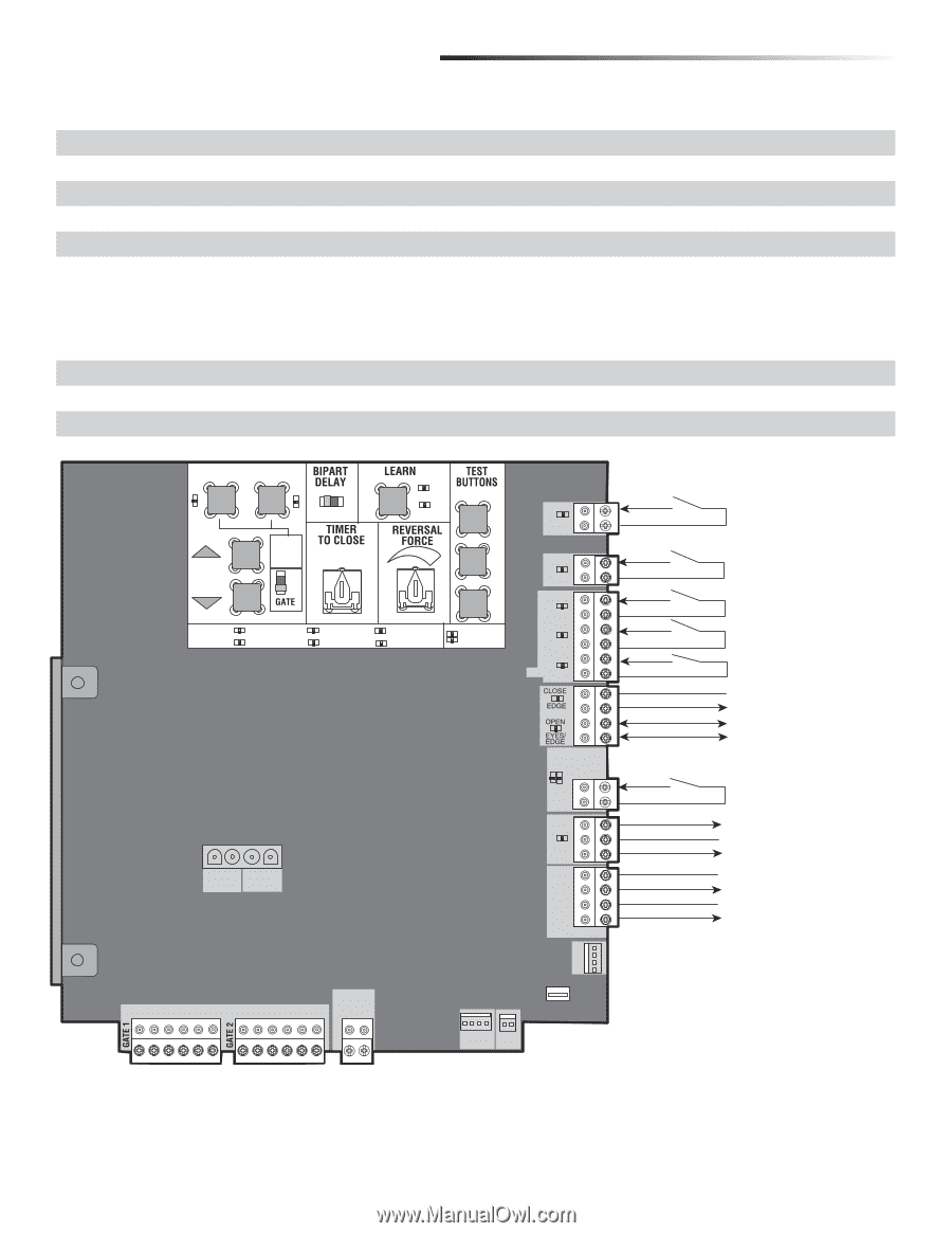
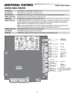
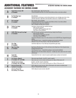
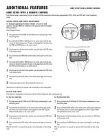
ADDITIONAL FEATURES CONTROL BOARD OVERVIEW CONTROL BOARD OVERVIEW SET OPEN Button SET CLOSE Button MOVE GATE Button BIPART DELAY Switch LEARN Button TIMER-TO-CLOSE dial REVERSAL FORCE dial TEST BUTTONS STATUS LEDs The SET OPEN button sets the OPEN limit. See Adjust Limits section. The SET CLOSE button sets the CLOSE limit. See Adjust Limits section. The MOVE GATE buttons will either open or close the gate when the operator is in Limit setting mode. See Adjust Limits section. The Bipart delay switch is used only for dual gates. See Bipart Delay section. The LEARN button is for programming remote controls and the network. The TIMER-TO-CLOSE (TTC) dial can be set to automatically close the gate after a specified time period. The TTC is factory set to OFF. If the TTC is set to the OFF position, then the gate will remain open until the operator receives another command from a control. Rotate the TIMER-TO-CLOSE dial to the desired setting. The range is 0 to 180 seconds, 0 seconds is OFF. NOTE: Any radio command, single button control, or CLOSE command on the control board prior to the TTC expiring will close the gate. The TTC is reset by any signals from the open controls, loops, close edges, and close photoelectric sensors (IR's). The REVERSAL FORCE dial adjusts the force. See Force Adjustment section. The TEST BUTTONS will operate the gate (OPEN, STOP and CLOSE). The STATUS LEDs are diagnostic codes for the operator. See Status LED Chart in the Troubleshooting section. OPEN CLOSE STOP SET OPEN SET CLOSE MOVE GATE OFF ON PRESS & RELEASE TO BEGIN LIMIT SETUP 1 2 (SECONDS) 10 5 60 XMITTER NETWORK STATUS: OFF INPUT POWER TIMER 180 MIN MAX BATT LOW BATT CHARGING GATE MOVING ACC PWR OVLD DIAGNOSTIC CODES SBC "FIRE DEPT " OPEN EXIT SHADOW CLOSE EYES/ INTERRUPT +- -+ J5 N.O. COM N.C. + BATT J15 + DC POWER ACCESSORY POWER + ON- + SW-. LOCK CLASS 2 SUPPLY 24 VOLTS SBC Com Fire Dept Com Exit Com Shadow Com Interrupt Com Open (+) Open (-) Close (+) Close (-) Comm Link Data A Comm Link Data B Lock N.C. (Maglock) Com Lock N.O. (Solenoid) Com (-) AccPower +24 Vdc Com (-) AccPower +24 Vdc A Single Button Control Station B Fire Dept. C Exit Loop D Shadow Loop E Interrupt Loop F Open Direction Safety G Close Direction Safety H Comm Link I Mag and J Solenoid Lock Acc. Power K Switched ON with gate motion. Always ON with expansion board connected. Switches Off to save L battery power if expansion board disconnected. Always ON EXP. BOARD BR GRN WT YE BLU RED BR GRN WT YE BLU RED SOLAR / CHARGER + GROUND ID RESET ALARM 30
-
 1
1 -
2
-
3
-
4
-
5
-
6
-
7
-
8
-
9
-
10
-
11
-
12
-
13
-
14
-
15
-
16
-
17
-
18
-
19
-
20
-
21
-
22
-
23
-
24
-
25
-
26
-
 27
27 -
 28
28 -
 29
29 -
 30
30 -
 31
31 -
 32
32 -
 33
33 -
 34
34 -
 35
35 -
 36
36 -
 37
37 -
38
-
39
-
40
-
41
-
42
-
43
-
44
-
45
-
46
-
47
-
48
 |
 |