MSI H67MS User Guide - Page 32
S/PDIF-Out Connector: JSP1
 |
View all MSI H67MS manuals
Add to My Manuals
Save this manual to your list of manuals |
Page 32 highlights
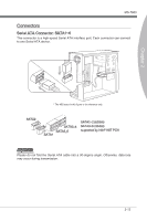
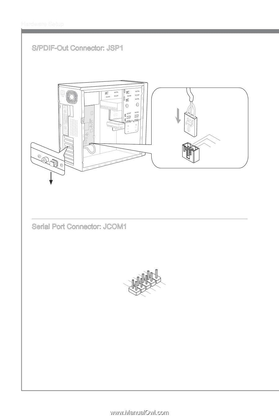
115V Hardware Setup S/PDIF-Out Connector: JSP1 This connector is used to connect S/PDIF (Sony & Philips Digital Interconnect Format) interface for digital audio transmission. 3.V2C.S1C.PGDrIoFund * The MB layout in this figure is for reference only. S/PDIF-Out Bracket (optional) Serial Port Connector: JCOM1 This connector is a 16550A high speed communication port that sends/receives 16 bytes FIFOs. You can attach a serial device. 2.S4I.ND6T.DR8S1.C0RT.NSo Pin 1.D3.CS5DO.G7Ur.RTo9uT.RnSdI 2-16
-
 1
1 -
2
-
3
-
4
-
5
-
6
-
7
-
8
-
9
-
10
-
11
-
12
-
13
-
14
-
15
-
16
-
17
-
18
-
19
-
20
-
21
-
22
-
23
-
24
-
25
-
26
-
 27
27 -
 28
28 -
 29
29 -
 30
30 -
 31
31 -
 32
32 -
 33
33 -
 34
34 -
 35
35 -
 36
36 -
 37
37 -
38
-
39
-
40
-
41
-
42
-
43
-
44
-
45
-
46
-
47
-
48
-
49
-
50
-
51
-
52
-
53
-
54
-
55
-
56
-
57
-
58
-
59
-
60
-
61
-
62
-
63
-
64
-
65
-
66
-
67
-
68
-
69
-
70
-
71
-
72
-
73
-
74
-
75
-
76
-
77
-
78
 |
 |
2-16
Hardware Setup
S/PDIF-Out Connector: JSP1
Th±s connector ±s used to connect S/PDIF (Sony & Ph±l±ps D±g±tal Interconnect Format)
±nterface for d±g±tal aud±o transm±ss±on.
3.VCC
2.SPDIF
1.Ground
* The MB layout ±n th±s figure ±s for reference only.
S/PDIF-Out Bracket (opt±onal)
Ser±al Port Connector: JCOM1
Th±s connector ±s a 16550A h±gh speed commun±cat±on port that sends/rece±ves 16
bytes FIFOs. You can attach a ser±al dev±ce.
1.DCD
3.SOUT
10.No Pin
5.Ground
7.RTS
9.RI
8.CTS
6.DSR
4.DTR
2.SIN