Maytag MAH5500BWW Service Manual - Page 64
Drain Hose - pump
 |
View all Maytag MAH5500BWW manuals
Add to My Manuals
Save this manual to your list of manuals |
Page 64 highlights
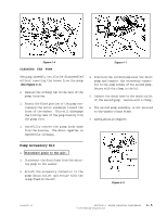
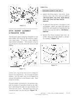
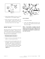
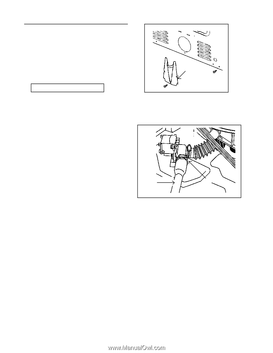
DRAIN HOSE The drain hose attaches to the pump and is routed through the lower rear wall of the cabinet. The drain hose is protected externally by a shield. REMOVAL 1. Disconnect power to the unit. 2. Remove the four ¼" hex head screws securing the access panel to the rear wall of the cabinet. 3. Remove the ¼" hex head screw securing the drain hose shield. Remove shield. 4. With access into the machine compartment, spread a towel under the connection of the drain hose to the pump. Loosen the clamp and remove the drain hose (Figure 6-10). 5. Reverse the previous steps for replacement. Drain Hose Drain Hose Access Cover Figure 6-9 Clamp Figure 6-10 16008373-01 SECTION 6. WATER CARRYING COMPONENTS 6-6 © 1998 Maytag Corporation
-
 1
1 -
2
-
3
-
4
-
5
-
6
-
7
-
8
-
9
-
10
-
11
-
12
-
13
-
14
-
15
-
16
-
17
-
18
-
19
-
20
-
21
-
22
-
23
-
24
-
25
-
26
-
27
-
28
-
29
-
30
-
31
-
32
-
33
-
34
-
35
-
36
-
37
-
38
-
39
-
40
-
41
-
42
-
43
-
44
-
45
-
46
-
47
-
48
-
49
-
50
-
51
-
52
-
53
-
54
-
55
-
56
-
57
-
58
-
 59
59 -
 60
60 -
 61
61 -
 62
62 -
 63
63 -
 64
64 -
 65
65 -
 66
66 -
 67
67 -
 68
68 -
 69
69 -
70
-
71
-
72
-
73
-
74
-
75
-
76
-
77
-
78
-
79
-
80
-
81
-
82
-
83
-
84
-
85
-
86
-
87
-
88
-
89
-
90
-
91
-
92
-
93
-
94
-
95
-
96
-
97
-
98
-
99
-
100
-
101
-
102
-
103
-
104
-
105
-
106
-
107
-
108
-
109
-
110
-
111
-
112
-
113
-
114
-
115
-
116
-
117
-
118
-
119
-
120
-
121
-
122
-
123
-
124
-
125
-
126
-
127
-
128
-
129
-
130
-
131
-
132
-
133
-
134
-
135
-
136
-
137
-
138
-
139
-
140
-
141
-
142
-
143
-
144
-
145
-
146
-
147
-
148
-
149
-
150
-
151
-
152
-
153
-
154
-
155
-
156
-
157
 |
 |
© 1998 Maytag Corporation
16008373-01
SECTION 6.
WATER CARRYING COMPONENTS
6-6
Figure 6-9
Drain Hose
Access
Cover
Figure 6-10
Drain Hose
Clamp
DRAIN HOSE
The drain hose attaches to the pump and is
routed through the lower rear wall of the cabi-
net. The drain hose is protected externally by
a shield.
REMOVAL
1.
Disconnect power to the unit.
2.
Remove the four ¼" hex head screws se-
curing the access panel to the rear wall of
the cabinet.
3.
Remove the ¼" hex head screw securing
the drain hose shield. Remove shield.
4.
With access into the machine compart-
ment, spread a towel under the connec-
tion of the drain hose to the pump. Loosen
the clamp and remove the drain hose
(Fig-
ure 6-10).
5.
Reverse the previous steps for
replacement.