Maytag MAH5500BWW Service Manual - Page 36
See Timer Input, Charts., See Water, Temperature Inputs. - door latch
 |
View all Maytag MAH5500BWW manuals
Add to My Manuals
Save this manual to your list of manuals |
Page 36 highlights
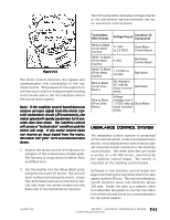
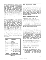
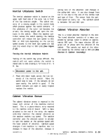
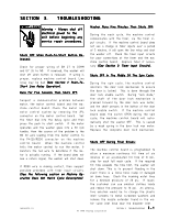
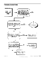
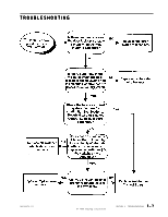
Tumbles Only: Excessive Vibration: When the door lock mechanism is in the "locked" mode, the wax motor has extended, forcing the latch axle to engage the door lock enable switch. This ensures the door is fully locked and the switch can then complete the signal back to the machine control board indicating the door is locked. Check connector P3(7)/YL 36 wire to verify if the terminal is making good contact to the board terminal. Check the door lock enable switch for continuity when the button is depressed. Replace door lock mechanism if necessary. ContinuesTo Tumble After The Wash Cycle Is Finished: Check for a stuck button on the door lock enable switch in the door lock mechanism. You can verify this at the machine control board by checking for continuity across P3(7)/YL 36 to P3(1)/RD23. If the door is unlocked and there is continuity, the switch button is stuck. At the end of the wash cycle, the machine control monitors the door lock enable switch for disengagement. If the switch is stuck, the washer will continue to tumble till the door unlocks, even though the door is actually unlocked. Replace the door lock mechanism. Third Rinse Cycle Is Always Cold: If the user rotates the timer dial to the third or fourth rinse, the water will always be cold regardless of temperature selection. The machine control board counts the number of rinses through the wash cycle. When the third and fourth rinse are reached, the board will check the rinse temperature selection for proper fill temperature (See Section 1:Water Temperature Inputs). Ensure that shipping bolts and straps have been removed from the washer. Check the levelness of the washer and ensure the leveling leg nuts are tightened up against the cabinet. Check the tightness of the upper and lower weights on the outer tub. Check for loose cabinet screws. Place hand on side of cabinet to determine if vibration noise due to cabinet flex. Apply sound dampening pad to inner cabinet wall if necessary. Check the unbalance circuit and wiring for continuity at the machine control (P2(4) to P3(1). Continuity should be present. If not, check the wiring connections at the strut, outer tub and interial unbalance switches. If a switch is bad or a wire off, the machine control will not know when an unbalance occurs. The machine control board checks the state of the circuit prior to beginning the spin cycle, then monitors the circuit throughout the cycle. If the circuit is OPEN, the board will not see "a change in state" whenever one of the normally-closed switches is activated during an unbalanced load condition. Machine Operation Does Not Match Cycle Description: The machine control board monitors where the timer is in the cycle and then uses this information to start different operations, such as drain, fill, tumble and spin. Four input wires from the timer to the machine control board inform the machine control board where the timer is in the wash cycle. However, if one or more of these wires are making an intermittant contact with the machine control board, the board can be "misinformed" and will not respond properly. Check the connections of the timer input wires leading from the timer to the machine control board (See Section 2: Timer Input Charts). Also, check wiring of all console switches to ensure no cross-wiring of 24 VDC and 120 VAC circuits. 16008373-01 © 1998 Maytag Corporation SECTION 3. TROUBLESHOOTING 3 - 2
-
 1
1 -
2
-
3
-
4
-
5
-
6
-
7
-
8
-
9
-
10
-
11
-
12
-
13
-
14
-
15
-
16
-
17
-
18
-
19
-
20
-
21
-
22
-
23
-
24
-
25
-
26
-
27
-
28
-
29
-
30
-
 31
31 -
 32
32 -
 33
33 -
 34
34 -
 35
35 -
 36
36 -
 37
37 -
 38
38 -
 39
39 -
 40
40 -
 41
41 -
42
-
43
-
44
-
45
-
46
-
47
-
48
-
49
-
50
-
51
-
52
-
53
-
54
-
55
-
56
-
57
-
58
-
59
-
60
-
61
-
62
-
63
-
64
-
65
-
66
-
67
-
68
-
69
-
70
-
71
-
72
-
73
-
74
-
75
-
76
-
77
-
78
-
79
-
80
-
81
-
82
-
83
-
84
-
85
-
86
-
87
-
88
-
89
-
90
-
91
-
92
-
93
-
94
-
95
-
96
-
97
-
98
-
99
-
100
-
101
-
102
-
103
-
104
-
105
-
106
-
107
-
108
-
109
-
110
-
111
-
112
-
113
-
114
-
115
-
116
-
117
-
118
-
119
-
120
-
121
-
122
-
123
-
124
-
125
-
126
-
127
-
128
-
129
-
130
-
131
-
132
-
133
-
134
-
135
-
136
-
137
-
138
-
139
-
140
-
141
-
142
-
143
-
144
-
145
-
146
-
147
-
148
-
149
-
150
-
151
-
152
-
153
-
154
-
155
-
156
-
157
 |
 |