Maytag MAH5500BWW Service Manual - Page 77
Machine, Control
 |
View all Maytag MAH5500BWW manuals
Add to My Manuals
Save this manual to your list of manuals |
Page 77 highlights
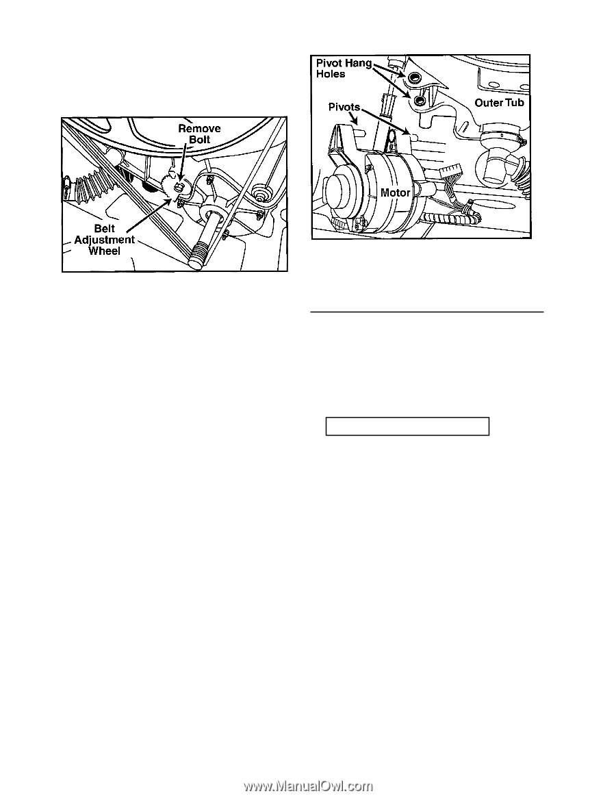
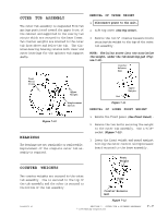
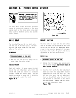
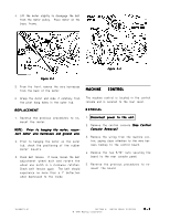
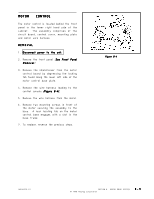
4 . Lift the motor slightly to disengage the belt from the motor pulley. Place motor on the base frame. Figure 8-3 Figure 8-2 5 . From the front, remove the wire harnesses from the back of the motor. 6 . Grasp the motor and slide it carefully from the pivot hang holes in the outer tub. REPLACEMENT 1 . Reverse the previous procedures to remount the motor. NOTE: Prior to hanging the motor, reconnect motor wire harnesses and ground wire. 2 . Prior to hanging the motor on the outer tub, check the positioning of the rubber motor mounts. 3 . Check belt tension. If loose, loosen the belt adjustment wheel bolt and rotate the wheel one notch in a clockwise rotation. Check belt tension again. The belt should experience no more than a 1" deflection when depressed to the inside. MACHINE CONTROL The machine control is located in the control console and is secured to the rear cover. REMOVAL 1 . Disconnect power to the unit. 2 . Remove the control console (See Control Console Removal). 3 . Remove the wiring from the machine control, paying close attention to the wire harness hookup to the control board. 4. Remove the two 5/16" nuts securing the board to the rear console panel. 5 . Reverse the previous procedures to remount the board. 16008373-01 SECTION 8. MOTOR DRIVE SYSYTEM © 1998 Maytag Corporation 8-2
-
 1
1 -
2
-
3
-
4
-
5
-
6
-
7
-
8
-
9
-
10
-
11
-
12
-
13
-
14
-
15
-
16
-
17
-
18
-
19
-
20
-
21
-
22
-
23
-
24
-
25
-
26
-
27
-
28
-
29
-
30
-
31
-
32
-
33
-
34
-
35
-
36
-
37
-
38
-
39
-
40
-
41
-
42
-
43
-
44
-
45
-
46
-
47
-
48
-
49
-
50
-
51
-
52
-
53
-
54
-
55
-
56
-
57
-
58
-
59
-
60
-
61
-
62
-
63
-
64
-
65
-
66
-
67
-
68
-
69
-
70
-
71
-
 72
72 -
 73
73 -
 74
74 -
 75
75 -
 76
76 -
 77
77 -
 78
78 -
 79
79 -
 80
80 -
 81
81 -
 82
82 -
83
-
84
-
85
-
86
-
87
-
88
-
89
-
90
-
91
-
92
-
93
-
94
-
95
-
96
-
97
-
98
-
99
-
100
-
101
-
102
-
103
-
104
-
105
-
106
-
107
-
108
-
109
-
110
-
111
-
112
-
113
-
114
-
115
-
116
-
117
-
118
-
119
-
120
-
121
-
122
-
123
-
124
-
125
-
126
-
127
-
128
-
129
-
130
-
131
-
132
-
133
-
134
-
135
-
136
-
137
-
138
-
139
-
140
-
141
-
142
-
143
-
144
-
145
-
146
-
147
-
148
-
149
-
150
-
151
-
152
-
153
-
154
-
155
-
156
-
157
 |
 |