Maytag MAH5500BWW Service Manual - Page 56
Front Shroud Assembly - door seal
 |
View all Maytag MAH5500BWW manuals
Add to My Manuals
Save this manual to your list of manuals |
Page 56 highlights
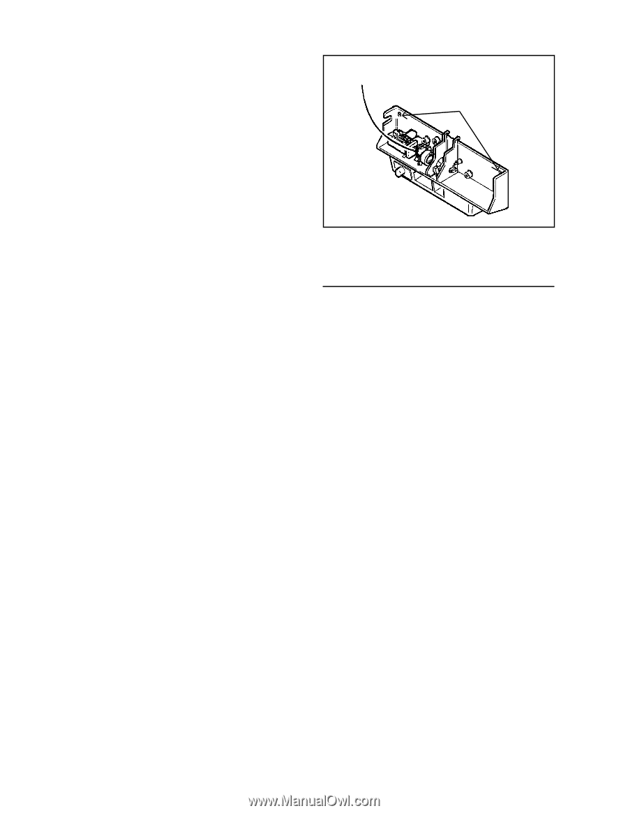
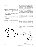
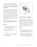
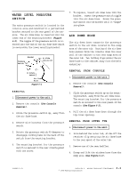
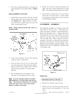
Two switches in the door lock mechanism inform the machine microprocessor control when the door is latched shut and when the door is securely locked. For more information, refer to section on Electrical-Mechanical Troubleshooting. An emergency access cord (filament) is attached to the sliding gear, should the wax motor fail in the extended position and entry into the washer is necessary. To gain access to the cable, removal of the dispenser bezel is necessary. Once removed, the cable is exposed. By carefully applying both a steady pull of the access cord and opening force to the door, the wax motor is overridden and the sliding gear is pulled from right to left away from engagement with the rotating gear. Thus, allowing the rotating gear to release the wire loop of the door. NOTE: When the cord is released, the lock will return to a locked position (Figure 5-8). REMOVAL 1. Remove the front panel and raise the top cover to expose the door lock mechanism (See Front Panel & Top Cover). 2. Remove the wires from the lock switches, wax motor and light fixture. 3. Remove light. 4. Remove two 5/16" hex-head screws securing the switch support to the metal shroud support (Figure 5-8). Emergency Access Cord Mounting Screws Figure 5-8 FRONT SHROUD ASSEMBLY The shroud assembly ties the sides of the cabinet together across the front for stability and provides support for mounting of the door assembly, front panel and door lock mechanism. To gain access to components behind the front shroud, the assembly can be removed as a whole assembly and lifted onto the top of the washer. This will allow access to the tub cover, spin basket, sump area and etc.. REMOVAL 1. Remove the front panel and raise the top cover to expose the front shroud assembly (See Front Panel & Top Cover). 2. With the door open, unsnap the boot gasket from around the inside perimeter of the door opening by pulling out on the sealing lip of the gasket (Figure 5-9). 16008373-01 © 1998 Maytag Corporation SECTION 5. CABINET ASSEMBLY 5 - 4
-
 1
1 -
2
-
3
-
4
-
5
-
6
-
7
-
8
-
9
-
10
-
11
-
12
-
13
-
14
-
15
-
16
-
17
-
18
-
19
-
20
-
21
-
22
-
23
-
24
-
25
-
26
-
27
-
28
-
29
-
30
-
31
-
32
-
33
-
34
-
35
-
36
-
37
-
38
-
39
-
40
-
41
-
42
-
43
-
44
-
45
-
46
-
47
-
48
-
49
-
50
-
 51
51 -
 52
52 -
 53
53 -
 54
54 -
 55
55 -
 56
56 -
 57
57 -
 58
58 -
 59
59 -
 60
60 -
 61
61 -
62
-
63
-
64
-
65
-
66
-
67
-
68
-
69
-
70
-
71
-
72
-
73
-
74
-
75
-
76
-
77
-
78
-
79
-
80
-
81
-
82
-
83
-
84
-
85
-
86
-
87
-
88
-
89
-
90
-
91
-
92
-
93
-
94
-
95
-
96
-
97
-
98
-
99
-
100
-
101
-
102
-
103
-
104
-
105
-
106
-
107
-
108
-
109
-
110
-
111
-
112
-
113
-
114
-
115
-
116
-
117
-
118
-
119
-
120
-
121
-
122
-
123
-
124
-
125
-
126
-
127
-
128
-
129
-
130
-
131
-
132
-
133
-
134
-
135
-
136
-
137
-
138
-
139
-
140
-
141
-
142
-
143
-
144
-
145
-
146
-
147
-
148
-
149
-
150
-
151
-
152
-
153
-
154
-
155
-
156
-
157
 |
 |