Maytag MAH5500BWW Service Manual - Page 49

Console

Page 49 highlights

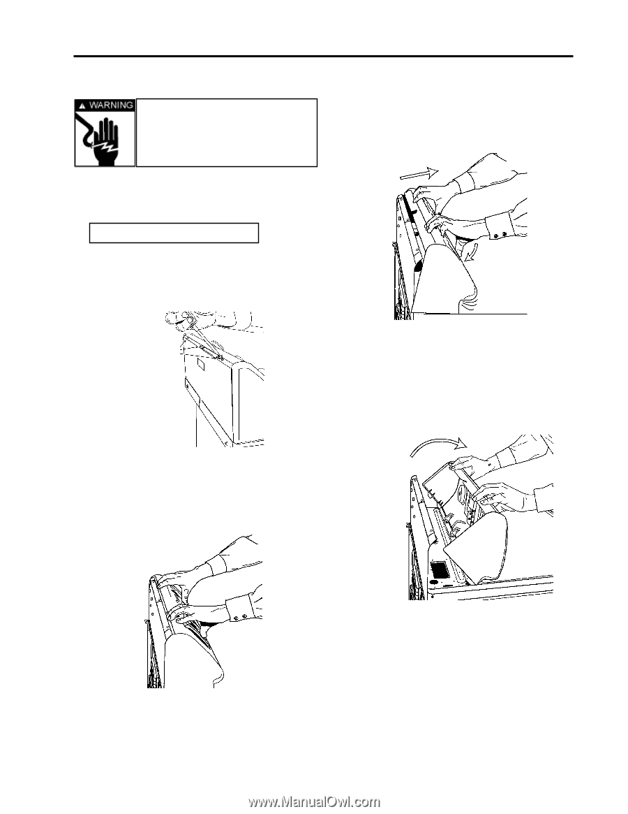
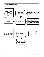
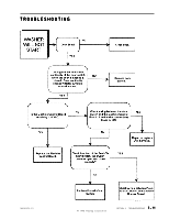
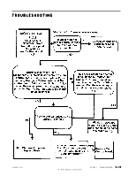
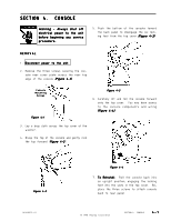
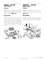
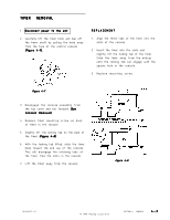
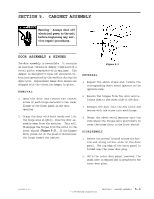
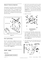
SECTION 4. CONSOLE Warning - Always shut off electrical power to the unit before beginning any service procedure. 5 . Push the bottom of the console toward the back panel to disengage the six locking feet from the top cover (Figure 4-3). REMOVAL 1 . Disconnect power to the unit. 2 . Remove the three screws securing the console rear cover plate across the rear top edge of the console (Figure 4-1). Console Mounting Screws Figure 4-1 Figure 4-3 6 . Carefully lift and roll the console forward onto the top cover. You now have access to the console components and wiring (Figure 4-4). 3 . Lay a drop cloth across the top cover of the washer. 4 . Grasp the top of the console and gently rock the top forward (Figure 4-2). Figure 4-2 16008373-01 Figure 4-4 7 . To Reinstall: Roll the console back into an upright position, engaging the locking feet into the slots in the top cover. Replace the three screws to attach console back to rear panel. © 1998 Maytag Corporation SECTION 4. CONSOLE 4-1

  • 1
  • 2
  • 3
  • 4
  • 5
  • 6
  • 7
  • 8
  • 9
  • 10
  • 11
  • 12
  • 13
  • 14
  • 15
  • 16
  • 17
  • 18
  • 19
  • 20
  • 21
  • 22
  • 23
  • 24
  • 25
  • 26
  • 27
  • 28
  • 29
  • 30
  • 31
  • 32
  • 33
  • 34
  • 35
  • 36
  • 37
  • 38
  • 39
  • 40
  • 41
  • 42
  • 43
  • 44
  • 45
  • 46
  • 47
  • 48
  • 49
  • 50
  • 51
  • 52
  • 53
  • 54
  • 55
  • 56
  • 57
  • 58
  • 59
  • 60
  • 61
  • 62
  • 63
  • 64
  • 65
  • 66
  • 67
  • 68
  • 69
  • 70
  • 71
  • 72
  • 73
  • 74
  • 75
  • 76
  • 77
  • 78
  • 79
  • 80
  • 81
  • 82
  • 83
  • 84
  • 85
  • 86
  • 87
  • 88
  • 89
  • 90
  • 91
  • 92
  • 93
  • 94
  • 95
  • 96
  • 97
  • 98
  • 99
  • 100
  • 101
  • 102
  • 103
  • 104
  • 105
  • 106
  • 107
  • 108
  • 109
  • 110
  • 111
  • 112
  • 113
  • 114
  • 115
  • 116
  • 117
  • 118
  • 119
  • 120
  • 121
  • 122
  • 123
  • 124
  • 125
  • 126
  • 127
  • 128
  • 129
  • 130
  • 131
  • 132
  • 133
  • 134
  • 135
  • 136
  • 137
  • 138
  • 139
  • 140
  • 141
  • 142
  • 143
  • 144
  • 145
  • 146
  • 147
  • 148
  • 149
  • 150
  • 151
  • 152
  • 153
  • 154
  • 155
  • 156
  • 157

© 1998 Maytag Corporation
16008373-01
SECTION 4.
CONSOLE
4-1
4-1
4-1
4-1
4-1
SECTION 4.
CONSOLE
SECTION 4.
CONSOLE
SECTION 4.
CONSOLE
SECTION 4.
CONSOLE
SECTION 4.
CONSOLE
REMOVAL
REMOVAL
REMOVAL
REMOVAL
REMOVAL
1 . Disconnect power to the unit.
Disconnect power to the unit.
2. Remove the three screws securing the con-
sole rear cover plate across the rear top
edge of the console
(Figure 4-1)
(Figure 4-1)
(Figure 4-1)
(Figure 4-1)
(Figure 4-1)
.
3.
Lay a drop cloth across the top cover of the
washer.
4.
Grasp the top of the console and gently rock
the top forward
(Figure 4-2
Figure 4-2
Figure 4-2
Figure 4-2
Figure 4-2).
Warning
Warning
Warning
Warning
Warning
- Always shut off
- Always shut off
- Always shut off
- Always shut off
- Always shut off
electrical power to the unit
before beginning any service
procedure.
procedure.
procedure.
procedure.
procedure.
Figure 4-2
Figure 4-2
Figure 4-2
Figure 4-2
Figure 4-2
Figure 4-3
Figure 4-3
Figure 4-3
Figure 4-3
Figure 4-3
Figure 4-4
Figure 4-4
Figure 4-4
Figure 4-4
Figure 4-4
Figure 4-1
Figure 4-1
Figure 4-1
Figure 4-1
Figure 4-1
Console
Console
Console
Console
Console
Mounting
Mounting
Mounting
Mounting
Mounting
Screws
Screws
Screws
Screws
Screws
5. Push the bottom of the console toward
the back panel to disengage the six lock-
ing feet from the top cover
(Figure 4-3)
(Figure 4-3)
(Figure 4-3)
(Figure 4-3)
(Figure 4-3)
.
6 . Carefully lift and roll the console forward
onto the top cover.
You now have access
to the console components and wiring
(Figure 4-4).
(Figure 4-4).
(Figure 4-4).
(Figure 4-4).
(Figure 4-4).
7. To Reinstall:
To Reinstall:
To Reinstall:
To Reinstall:
To Reinstall:
Roll the console back into
an upright position, engaging the locking
feet into the slots in the top cover.
Re-
place the three screws to attach console
back to rear panel.