Maytag MAH5500BWW Service Manual - Page 22
Water Valve Test, Voltage Checks, Wax Motor Check - Door Lock, Mechanism, Grounded Components - has no display
 |
View all Maytag MAH5500BWW manuals
Add to My Manuals
Save this manual to your list of manuals |
Page 22 highlights
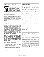
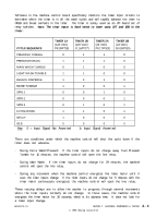
ELECTRICAL TESTS Water Valve Test Warning - Always shut off electrical power to the unit before beginning any service repair procedures. Grounded Components When performing service diagnostics, replacements and repairs, always check to determine whether all ground wires linking panel and components are reattached if removed. Voltage Checks Generally, these checks will consist of taking readings at the wall receptacle to determine the availability of voltage to the product. Voltage checks on individual components of a product are not recommended due to the possibility of electrical shock. Component part testing is best accomplished through continuity checks with an Appliance Test Meter (See Electrical Test Equipment). NOTE: Use of the meter on voltage higher than the indicated range may cause permanent damage to the meter. To prevent damage, first select the highest range and then lower the range for readings which fall within the lower scale. Set up meter for use as follows: 1. Turn selector knob to desired meter function and appropriate range. 2. Plug black lead into socket marked black (-). Check the water valve for electrical continuity. This check should be made with the electrical supply disconnected from the washer. Remove the wire harness from the water valve terminals and place the ohm meter probes on the terminals of the water valve. The water valve solenoid coil should have a resistance between 500-1000 ohms. If no ohms are shown on the display of the electrical test meter, the solenoid coil has an open winding and the valve should be replaced. The thermistor in the water valve changes in resistance in direct relationship to water temperatures. To monitor the performance of the thermistor, run a partial hot water fill and check the ohm resistance of the thermistor circuit. Then, run a cold water fill and measure the resistance again. There should be a notable difference in the resistance readings. To check the ohm resistance, pull the P2 wire harness connector off the machine control and locate the P2(5) and P2(6) leads in the connector (Figure 2-3). Wax Motor Check - Door Lock Mechanism Check the wax motor for proper resistance. This check should be made with the electrical supply disconnected from the washer. Remove the wire harness from the wax motor terminals and place the ohm meter probes on the terminals of the wax motor. The wax motor should have a resistance of approximately 1900 ohms at room temperature. To check wax motors through console, see section: Machine Control page 2-5. 3. Plug red lead into socket marked red (+). 4. Place test leads into receptacle to determine voltage available. 16008373-01 SECTION 2. ELECTRICAL COMPONENTS & TESTING © 1998 Maytag Corporation 2-2
-
 1
1 -
2
-
3
-
4
-
5
-
6
-
7
-
8
-
9
-
10
-
11
-
12
-
13
-
14
-
15
-
16
-
 17
17 -
 18
18 -
 19
19 -
 20
20 -
 21
21 -
 22
22 -
 23
23 -
 24
24 -
 25
25 -
 26
26 -
 27
27 -
28
-
29
-
30
-
31
-
32
-
33
-
34
-
35
-
36
-
37
-
38
-
39
-
40
-
41
-
42
-
43
-
44
-
45
-
46
-
47
-
48
-
49
-
50
-
51
-
52
-
53
-
54
-
55
-
56
-
57
-
58
-
59
-
60
-
61
-
62
-
63
-
64
-
65
-
66
-
67
-
68
-
69
-
70
-
71
-
72
-
73
-
74
-
75
-
76
-
77
-
78
-
79
-
80
-
81
-
82
-
83
-
84
-
85
-
86
-
87
-
88
-
89
-
90
-
91
-
92
-
93
-
94
-
95
-
96
-
97
-
98
-
99
-
100
-
101
-
102
-
103
-
104
-
105
-
106
-
107
-
108
-
109
-
110
-
111
-
112
-
113
-
114
-
115
-
116
-
117
-
118
-
119
-
120
-
121
-
122
-
123
-
124
-
125
-
126
-
127
-
128
-
129
-
130
-
131
-
132
-
133
-
134
-
135
-
136
-
137
-
138
-
139
-
140
-
141
-
142
-
143
-
144
-
145
-
146
-
147
-
148
-
149
-
150
-
151
-
152
-
153
-
154
-
155
-
156
-
157
 |
 |