Motorola V186 User Manual - Page 120
IP Conversion Tables, not specify this address
 |
View all Motorola V186 manuals
Add to My Manuals
Save this manual to your list of manuals |
Page 120 highlights
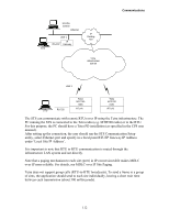
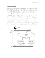
Communications IP Conversion Tables The IP conversion table is created in the ACE3600 STS using the IP Conversion Table Manager. Note that unlike the network configuration, there is no default, and any IP conversion tables must be created manually. The IP conversion table maps sites in the system (site ID+link ID) to IP addresses or host names. Each site ID/link ID pair can have one unique entry in the table, though an IP address can appear in more than one row. A site ID of 0 is reserved for a group call. In RS232/PPP and Ethernet DHCP, the IP address is read from the network once it is connected to the RTU. In Astro IV&D, this is not the real IP address set by the infrastructure; rather, it is a dummy address configured in the radio via the CPS Mobile Computer IP address which is (by default 192.168.128.2). In the IP conversion table do not specify this address, but the actual IP address assigned by the infrastructure operator. The ACE3600 IP conversion table format includes a link ID column which allows more than one port in the same site to be connected to LAN or to PPP. Any legacy MOSCAD RTU or IP Gateway in the network must defined using its own Toolbox IP Conversion Table utility. FEP 100 LINE 2 Control Center LINE 1 CEN LAN FEP 10.5.1.xx Packet Data Network 192.5.1.xx LAN 155.9.1.xx LINE 2 Subscriber Radio 1 LINE 1 PPP/RS-232 PEI RTU-A Subscriber Radio 2 LINE 1 PPP/RS-232 PEI RTU-B LINE 2 116
-
 1
1 -
2
-
3
-
4
-
5
-
6
-
7
-
8
-
9
-
10
-
11
-
12
-
13
-
14
-
15
-
16
-
17
-
18
-
19
-
20
-
21
-
22
-
23
-
24
-
25
-
26
-
27
-
28
-
29
-
30
-
31
-
32
-
33
-
34
-
35
-
36
-
37
-
38
-
39
-
40
-
41
-
42
-
43
-
44
-
45
-
46
-
47
-
48
-
49
-
50
-
51
-
52
-
53
-
54
-
55
-
56
-
57
-
58
-
59
-
60
-
61
-
62
-
63
-
64
-
65
-
66
-
67
-
68
-
69
-
70
-
71
-
72
-
73
-
74
-
75
-
76
-
77
-
78
-
79
-
80
-
81
-
82
-
83
-
84
-
85
-
86
-
87
-
88
-
89
-
90
-
91
-
92
-
93
-
94
-
95
-
96
-
97
-
98
-
99
-
100
-
101
-
102
-
103
-
104
-
105
-
106
-
107
-
108
-
109
-
110
-
111
-
112
-
113
-
114
-
 115
115 -
 116
116 -
 117
117 -
 118
118 -
 119
119 -
 120
120 -
 121
121 -
 122
122 -
 123
123 -
 124
124 -
 125
125 -
126
-
127
-
128
-
129
-
130
-
131
-
132
-
133
-
134
-
135
-
136
-
137
-
138
-
139
-
140
-
141
-
142
-
143
-
144
-
145
-
146
-
147
-
148
-
149
-
150
-
151
-
152
-
153
-
154
-
155
-
156
-
157
-
158
-
159
-
160
-
161
-
162
-
163
-
164
-
165
-
166
-
167
-
168
-
169
-
170
-
171
-
172
-
173
-
174
-
175
-
176
-
177
-
178
-
179
-
180
-
181
-
182
-
183
-
184
-
185
 |
 |
