Motorola V186 User Manual - Page 160
DI Module Specifications, or 40 Wire Cable with TB Holder connector, 26 AWG wires
 |
View all Motorola V186 manuals
Add to My Manuals
Save this manual to your list of manuals |
Page 160 highlights
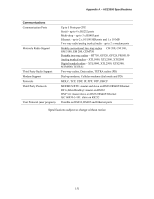
Appendix A - ACE3600 Specifications DI Module Specifications 16/32 DI FAST 24V Modules Total Number of Inputs 16 DI (Option V265); 32 DI (Option V379) Input Arrangement Isolated groups of 16 inputs with shared common Fast Counter Inputs Inputs that can be used as fast counters: - All inputs in 16 DI module; - First 20 inputs in 32 DI module AC Input Frequency 45 - 65 Hz AC Input Delay Maximum 0.2 mS Fast Counter Input Frequency 0 - 12.5 KHz, minimum pulse width 40 µS Max. DC Input Voltage Max. ±40 V DC (relative to input common) "ON" DC Voltage Range +9 to +30 V DC, -30 to -9 V DC "OFF" DC Voltage Range -3 to +3 V DC "ON" AC Voltage Range 10 to 27 V AC (RMS) "OFF" AC Voltage Range 0 to 5 V AC (RMS) Input Current Max. 3.5 mA Fast Capture Resolution 1 mS (Interrupt upon change of state) Event Time Tagging Resolution 1 mS (Interrupt upon change of state) Input Filtering 0 to 50.8 mS (DC, programmable in 0.2 mSec steps) Counter Input Filtering 0 to 12.75 mS (programmable in 0.05 mSec steps for inputs configured as high speed counters) 24 V DC Output Supports optional isolated 24 V plug-in "Wetting" Power Supply (one in 16 DI, two in 32 DI) Diagnostic LEDs Status LED per each input, module error LED, 24V plug-in status LED User Connection 2 or 4 Terminal Blocks (3.5mm pitch), Maximum 18 AWG Cable and TB Holder 20 or 40 Wire Cable with TB Holder connector, 26 AWG wires Module Replacement Hot swap replacement - module extraction/insertion under voltage Input Isolation 2.5 kV RMS between input and module logic per IEC60255-5 Input Insulation Insulation resistance 100 MΩ @ 500 V DC, per IEC60255-5 Operating Voltage 10.8-16 V DC and 3.3 V DC (from the motherboard connector) Power Consumption Refer to Appendix C: ACE3600 Maximum Power Ratings. Dimensions 37 mm W x 225 mm H x 180 mm D, (1.5" W x 8.7" H x 7.1" D) 156
-
 1
1 -
2
-
3
-
4
-
5
-
6
-
7
-
8
-
9
-
10
-
11
-
12
-
13
-
14
-
15
-
16
-
17
-
18
-
19
-
20
-
21
-
22
-
23
-
24
-
25
-
26
-
27
-
28
-
29
-
30
-
31
-
32
-
33
-
34
-
35
-
36
-
37
-
38
-
39
-
40
-
41
-
42
-
43
-
44
-
45
-
46
-
47
-
48
-
49
-
50
-
51
-
52
-
53
-
54
-
55
-
56
-
57
-
58
-
59
-
60
-
61
-
62
-
63
-
64
-
65
-
66
-
67
-
68
-
69
-
70
-
71
-
72
-
73
-
74
-
75
-
76
-
77
-
78
-
79
-
80
-
81
-
82
-
83
-
84
-
85
-
86
-
87
-
88
-
89
-
90
-
91
-
92
-
93
-
94
-
95
-
96
-
97
-
98
-
99
-
100
-
101
-
102
-
103
-
104
-
105
-
106
-
107
-
108
-
109
-
110
-
111
-
112
-
113
-
114
-
115
-
116
-
117
-
118
-
119
-
120
-
121
-
122
-
123
-
124
-
125
-
126
-
127
-
128
-
129
-
130
-
131
-
132
-
133
-
134
-
135
-
136
-
137
-
138
-
139
-
140
-
141
-
142
-
143
-
144
-
145
-
146
-
147
-
148
-
149
-
150
-
151
-
152
-
153
-
154
-
 155
155 -
 156
156 -
 157
157 -
 158
158 -
 159
159 -
 160
160 -
 161
161 -
 162
162 -
 163
163 -
 164
164 -
 165
165 -
166
-
167
-
168
-
169
-
170
-
171
-
172
-
173
-
174
-
175
-
176
-
177
-
178
-
179
-
180
-
181
-
182
-
183
-
184
-
185
 |
 |
