Motorola V186 User Manual - Page 60
I/O Expansion, Note: Only a dedicated LAN
 |
View all Motorola V186 manuals
Add to My Manuals
Save this manual to your list of manuals |
Page 60 highlights
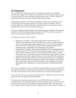
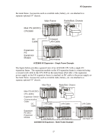
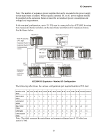
I/O Expansion The ACE3600 RTU includes the option of expanding the number of I/O modules controlled by a single CPU module on the main frame. The I/O expansion frames can be co-located with RTU on the main frame (installed in the same 19" rack or cabinet) or distributed in the same site (up to 50 meters from the main frame.) I/O expansion is based on a 100 Base-T full duplex Ethernet connection between the CPU module and the expansion modules. This type of connection enables the user program application to control and monitor the I/O modules on the expansion frames transparently as if they are located on the main frame. The user can diagnose all the modules on the expansion frames using the STS connected to the CPU on the main frame (locally or remotely.) The STS can also be connected locally to the expansion module's RS232 (STS1) port. I/O expansion is based on three modules: ƒ Expansion LAN Switch: This module is part of the expansion frame. It is installed in the main frame in an I/O module slot. Up to seven expansion frames can be connected through a single expansion LAN switch. (For one expansion frame, the switch is not required.) Eight to thirteen expansion frames can be connected using a combination of two expansion LAN switches. ƒ Expansion Power Supply: This module is installed in the I/O expansion frame. It extends power (and 12V DO control) from the power supply on the RTU's main frame to the I/O expansion frame, or from one I/O expansion frame to another. This module can be replaced by another ACE3600 power supply option per power requirements or when the expansion frame is not co-located with the main frame. ƒ Expansion Module: This module is part of the expansion frame. It is installed in the I/O expansion frame next to the power supply. It is connected via LAN to the RTU's main frame, either to the CPU module or to the expansion LAN switch, depending on the configuration. For more information, see Expansion Module below. Note: Only a dedicated LAN with ACE3600 components should be used by the main CPU and expansion modules to communicate with each other. Connecting other elements such as routers and other devices to the LAN may disrupt the I/O expansion system operation. Note: The main CPU must include an Eth1 Ethernet port. Therefore, only the CPU 3640 can be used for I/O expansion on the main frame. The figure below provides a general view of an ACE3600 CPU with a single I/O expansion frame. The expansion module on the I/O expansion frame is connected using a crossed LAN cable to the CPU3640 on the main frame (Port Eth1.) The expansion power supply on the I/O expansion frame is attached via DC cable to the power supply on 56
-
 1
1 -
2
-
3
-
4
-
5
-
6
-
7
-
8
-
9
-
10
-
11
-
12
-
13
-
14
-
15
-
16
-
17
-
18
-
19
-
20
-
21
-
22
-
23
-
24
-
25
-
26
-
27
-
28
-
29
-
30
-
31
-
32
-
33
-
34
-
35
-
36
-
37
-
38
-
39
-
40
-
41
-
42
-
43
-
44
-
45
-
46
-
47
-
48
-
49
-
50
-
51
-
52
-
53
-
54
-
 55
55 -
 56
56 -
 57
57 -
 58
58 -
 59
59 -
 60
60 -
 61
61 -
 62
62 -
 63
63 -
 64
64 -
 65
65 -
66
-
67
-
68
-
69
-
70
-
71
-
72
-
73
-
74
-
75
-
76
-
77
-
78
-
79
-
80
-
81
-
82
-
83
-
84
-
85
-
86
-
87
-
88
-
89
-
90
-
91
-
92
-
93
-
94
-
95
-
96
-
97
-
98
-
99
-
100
-
101
-
102
-
103
-
104
-
105
-
106
-
107
-
108
-
109
-
110
-
111
-
112
-
113
-
114
-
115
-
116
-
117
-
118
-
119
-
120
-
121
-
122
-
123
-
124
-
125
-
126
-
127
-
128
-
129
-
130
-
131
-
132
-
133
-
134
-
135
-
136
-
137
-
138
-
139
-
140
-
141
-
142
-
143
-
144
-
145
-
146
-
147
-
148
-
149
-
150
-
151
-
152
-
153
-
154
-
155
-
156
-
157
-
158
-
159
-
160
-
161
-
162
-
163
-
164
-
165
-
166
-
167
-
168
-
169
-
170
-
171
-
172
-
173
-
174
-
175
-
176
-
177
-
178
-
179
-
180
-
181
-
182
-
183
-
184
-
185
 |
 |
