Motorola V186 User Manual - Page 6
The Front End Processor FEP, System Tools Suite STS - software
 |
View all Motorola V186 manuals
Add to My Manuals
Save this manual to your list of manuals |
Page 6 highlights
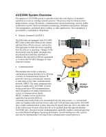
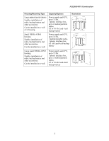
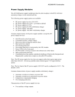
ACE3600 System Overview • The Front End Processor (FEP): The Front End Processor is used at the central site(s) to provide a two-way path to the communication system and the distant RTUs from the SCADA Manager hardware and software. The FEP converts MDLC protocol data from the RTUs to a protocol used by the SCADA Manager vendor: when the OPC or ModBus protocol is used, the FEP will maintain a local database of all the data from the multiple in-field sites; when TCP/IP gateway is used, the FEP is simply a gateway between the two different protocols. The FEP always acknowledges all RTU-initiated messages. The FEP can also provide a twoway path between the ACE3600 STS and the field RTUs for those functions unique to ACE3600 that are not provided by the SCADA Manager software (over-the-air programming download, diagnostics upload, and more.) • SCADA Manager: The SCADA Manager provides the operator with the display and report tools necessary to view and manage the associated process(es). The SCADA Manager obtains data from the FEP according to its needs and typically presents that data on custom-created display formats; control messages may also be initiated from these custom screens. Security is typically implemented via permission levels activated by the operator's sign-on password. Microsoft Windows is becoming the operating system of choice because it easily supports the desired graphic symbols used on the custom screens. The report capability may be provided by the SCADA software or a data export to Microsoft Excel or equivalent may be utilized. The end result is an easy to use pictorially-described representation of the field status of key equipment items plus the means to make changes in how those pieces of equipment operate. • System Tools Suite (STS): The ACE3600 STS is a software program that allows the system engineer to set up and maintain the ACE3600 system in accordance with system-specific requirements. The STS computer (PC) may be connected to any RTU/FEP or to the other network points in the system and have connectivity established with any other site through the store-&forward capability of the MDLC protocol; all the capabilities available during a local connection may then be enjoyed by the remotely-connected system engineer: the communication network topography may be defined; the application(s) for each site may be created and downloaded into the RTUs; run-time and diagnostic data may be uploaded. 2
-
 1
1 -
 2
2 -
 3
3 -
 4
4 -
 5
5 -
 6
6 -
 7
7 -
 8
8 -
 9
9 -
 10
10 -
 11
11 -
 12
12 -
13
-
14
-
15
-
16
-
17
-
18
-
19
-
20
-
21
-
22
-
23
-
24
-
25
-
26
-
27
-
28
-
29
-
30
-
31
-
32
-
33
-
34
-
35
-
36
-
37
-
38
-
39
-
40
-
41
-
42
-
43
-
44
-
45
-
46
-
47
-
48
-
49
-
50
-
51
-
52
-
53
-
54
-
55
-
56
-
57
-
58
-
59
-
60
-
61
-
62
-
63
-
64
-
65
-
66
-
67
-
68
-
69
-
70
-
71
-
72
-
73
-
74
-
75
-
76
-
77
-
78
-
79
-
80
-
81
-
82
-
83
-
84
-
85
-
86
-
87
-
88
-
89
-
90
-
91
-
92
-
93
-
94
-
95
-
96
-
97
-
98
-
99
-
100
-
101
-
102
-
103
-
104
-
105
-
106
-
107
-
108
-
109
-
110
-
111
-
112
-
113
-
114
-
115
-
116
-
117
-
118
-
119
-
120
-
121
-
122
-
123
-
124
-
125
-
126
-
127
-
128
-
129
-
130
-
131
-
132
-
133
-
134
-
135
-
136
-
137
-
138
-
139
-
140
-
141
-
142
-
143
-
144
-
145
-
146
-
147
-
148
-
149
-
150
-
151
-
152
-
153
-
154
-
155
-
156
-
157
-
158
-
159
-
160
-
161
-
162
-
163
-
164
-
165
-
166
-
167
-
168
-
169
-
170
-
171
-
172
-
173
-
174
-
175
-
176
-
177
-
178
-
179
-
180
-
181
-
182
-
183
-
184
-
185
 |
 |