Motorola V186 User Manual - Page 70
Note: The Eth.1 M port on the, expansion LAN switch ports Eth2-Eth8 respectively. - manual
 |
View all Motorola V186 manuals
Add to My Manuals
Save this manual to your list of manuals |
Page 70 highlights
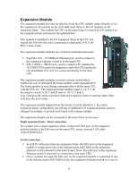
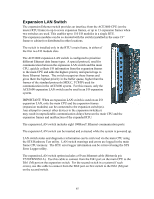
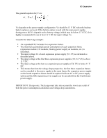
I/O Expansion One of three Ethernet cables can be used to connect an Ethernet port on the expansion LAN switch to an expansion module in an expansion frame. If the system includes one switch (for up to seven frames), ports Eth2-Eth8 are available. If the system includes two switches (for up to thirteen frames), ports Eth3-Eth8 are available on the first switch and ports Eth2-Eth8 are available on the second switch. Note: The Eth.1 (M) port on the expansion LAN switch is reserved for connection to the main CPU. For details on the Ethernet cables, see Expansion Module above. In systems with several expansion frames, the ACE3600 STS can be used to provide automatic switch connection configuration. The following physical connections are assumed: ƒ A system with one expansion frame is connected directly to the main CPU. ƒ A system with 1-7 frames (frame IDs 1-7) is connected via one switch (to expansion LAN switch ports Eth2-Eth8 respectively.) ƒ A system with 1-13 frames is connected via two switches (frame IDs 1-6 connected to expansion LAN switch 1 ports Eth3-Eth8 respectively and frame IDs 7-13 connected to expansion LAN switch 2 ports Eth2-Eth8 respectively.) If the expansion frames are not physically connected as described above, the switch connection must be manually configured in the STS Switch Connections dialog. For more information, see the ACE3600 STS User Guide. 66
-
 1
1 -
2
-
3
-
4
-
5
-
6
-
7
-
8
-
9
-
10
-
11
-
12
-
13
-
14
-
15
-
16
-
17
-
18
-
19
-
20
-
21
-
22
-
23
-
24
-
25
-
26
-
27
-
28
-
29
-
30
-
31
-
32
-
33
-
34
-
35
-
36
-
37
-
38
-
39
-
40
-
41
-
42
-
43
-
44
-
45
-
46
-
47
-
48
-
49
-
50
-
51
-
52
-
53
-
54
-
55
-
56
-
57
-
58
-
59
-
60
-
61
-
62
-
63
-
64
-
 65
65 -
 66
66 -
 67
67 -
 68
68 -
 69
69 -
 70
70 -
 71
71 -
 72
72 -
 73
73 -
 74
74 -
 75
75 -
76
-
77
-
78
-
79
-
80
-
81
-
82
-
83
-
84
-
85
-
86
-
87
-
88
-
89
-
90
-
91
-
92
-
93
-
94
-
95
-
96
-
97
-
98
-
99
-
100
-
101
-
102
-
103
-
104
-
105
-
106
-
107
-
108
-
109
-
110
-
111
-
112
-
113
-
114
-
115
-
116
-
117
-
118
-
119
-
120
-
121
-
122
-
123
-
124
-
125
-
126
-
127
-
128
-
129
-
130
-
131
-
132
-
133
-
134
-
135
-
136
-
137
-
138
-
139
-
140
-
141
-
142
-
143
-
144
-
145
-
146
-
147
-
148
-
149
-
150
-
151
-
152
-
153
-
154
-
155
-
156
-
157
-
158
-
159
-
160
-
161
-
162
-
163
-
164
-
165
-
166
-
167
-
168
-
169
-
170
-
171
-
172
-
173
-
174
-
175
-
176
-
177
-
178
-
179
-
180
-
181
-
182
-
183
-
184
-
185
 |
 |