Motorola V186 User Manual - Page 157
Status LED for: input voltage, AUX1 and AUX2 outputs, 12 V Control, No Load Power
 |
View all Motorola V186 manuals
Add to My Manuals
Save this manual to your list of manuals |
Page 157 highlights
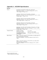
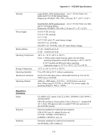
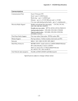
Appendix A - ACE3600 Specifications 18-72V DC Power Supply Modules Input Voltage 18-72 V DC Total Power Outputs Battery Charger 18-72 V DC Max. 60 W continuous; max. 105 W peak @ 25% duty cycle Motherboard connector (to CPU and I/O modules): 13.2 V DC ±20%, max. 4 A AUX1A/AUX1B: equal to input voltage, max. 8 A, on/off controlled by user program AUX2A/AUX2B (configurable): equal to input voltage (default), max. 8A, or 3.3 (default), 5, 7.5, 9 V DC ±10%, max. 2.5A, on/off (default) controlled by user program Note: max. 8 A total current consumption from all outputs 12 V Lead Acid battery charger (in PS model with charger) Automatic charging of 6.5 or 10 Ah backup battery, battery temperature sensing, overcharging protection, battery capacity test and diagnostics, automatic battery switch-over Diagnostic LEDs No Load Power Consumption Efficiency Status LED for: input voltage, AUX1 and AUX2 outputs, 12 V Control DO for DO modules, and battery Max. 250 mA 80% typical, 76% with full load Inrush Current Protection Output Protection Insulation Dimensions Weight 10 A maximum, for 2 mSec. Max, cold start at 25°C Internal line input fuse (replaceable), short circuit automatic recover AUX2A/B short circuit, automatic recovery on 3.3, 5, 7.5, 9 V Input to case: 500 V DC, input to output 500 V DC 56 mm W x 225 mm H x 180 mm D (2.2" W x 8.7" H x 7.1" D) Approx. 1Kg (2.2 Lb) Specifications subject to change without notice. 153
-
 1
1 -
2
-
3
-
4
-
5
-
6
-
7
-
8
-
9
-
10
-
11
-
12
-
13
-
14
-
15
-
16
-
17
-
18
-
19
-
20
-
21
-
22
-
23
-
24
-
25
-
26
-
27
-
28
-
29
-
30
-
31
-
32
-
33
-
34
-
35
-
36
-
37
-
38
-
39
-
40
-
41
-
42
-
43
-
44
-
45
-
46
-
47
-
48
-
49
-
50
-
51
-
52
-
53
-
54
-
55
-
56
-
57
-
58
-
59
-
60
-
61
-
62
-
63
-
64
-
65
-
66
-
67
-
68
-
69
-
70
-
71
-
72
-
73
-
74
-
75
-
76
-
77
-
78
-
79
-
80
-
81
-
82
-
83
-
84
-
85
-
86
-
87
-
88
-
89
-
90
-
91
-
92
-
93
-
94
-
95
-
96
-
97
-
98
-
99
-
100
-
101
-
102
-
103
-
104
-
105
-
106
-
107
-
108
-
109
-
110
-
111
-
112
-
113
-
114
-
115
-
116
-
117
-
118
-
119
-
120
-
121
-
122
-
123
-
124
-
125
-
126
-
127
-
128
-
129
-
130
-
131
-
132
-
133
-
134
-
135
-
136
-
137
-
138
-
139
-
140
-
141
-
142
-
143
-
144
-
145
-
146
-
147
-
148
-
149
-
150
-
151
-
 152
152 -
 153
153 -
 154
154 -
 155
155 -
 156
156 -
 157
157 -
 158
158 -
 159
159 -
 160
160 -
 161
161 -
 162
162 -
163
-
164
-
165
-
166
-
167
-
168
-
169
-
170
-
171
-
172
-
173
-
174
-
175
-
176
-
177
-
178
-
179
-
180
-
181
-
182
-
183
-
184
-
185
 |
 |
