Motorola V186 User Manual - Page 13
Status LEDS which indicate the CPU status during startup boot, run-time or - user guide
 |
View all Motorola V186 manuals
Add to My Manuals
Save this manual to your list of manuals |
Page 13 highlights
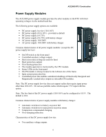
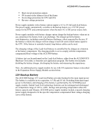
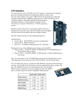
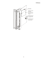
CPU Modules The CPU has a low drift RTC. The date and time are retained using an on-board rechargeable lithium battery. The CPU date and time can be set using the ACE3600 STS. The CPU can also be synchronized with other RTUs in the system, using the system clock. The CPU's rechargeable lithium battery provides backup power and data retention for the SRAM and RTC. Typically, the battery will preserve the data stored in the SRAM and RTC for 60 continuous days without power. When the SRAM option is not used, the Lithium battery will keep the Real Time Clock (RTC) running for a longer period of time. The CPU module also includes: ƒ Buzzer (audio indication), which is used to indicate task completion (such as end of download/upload, restart etc.) and can also be controlled from the user application program. ƒ Pushbuttons on the front panel, PB1 and PB2. These pushbuttons are used for activating and testing the module LEDs, restarting the unit, erasing the user Flash memory and activating memory test. The pushbuttons can also be monitored by the user application program (when it is running) for the application purposes. ƒ Status LEDS which indicate the CPU status during startup (boot), run-time or when there is a failure. Communication LEDs are used to indicate the communication port status. User LEDs can be used by the user application program. The CPU's firmware is a real-time multitasking operating system, based on the Wind River VxWorks OS. The CPU is shipped from the factory with the most recent firmware version, and it can be updated/replaced using a remote or local connection. Downloading firmware updates is performed using the STS. (See Downloading to a Site in the ACE3600 STS User Guide.) If the new firmware download stops or fails, the CPU will restart with the existing firmware. 9
-
 1
1 -
2
-
3
-
4
-
5
-
6
-
7
-
 8
8 -
 9
9 -
 10
10 -
 11
11 -
 12
12 -
 13
13 -
 14
14 -
 15
15 -
 16
16 -
 17
17 -
 18
18 -
19
-
20
-
21
-
22
-
23
-
24
-
25
-
26
-
27
-
28
-
29
-
30
-
31
-
32
-
33
-
34
-
35
-
36
-
37
-
38
-
39
-
40
-
41
-
42
-
43
-
44
-
45
-
46
-
47
-
48
-
49
-
50
-
51
-
52
-
53
-
54
-
55
-
56
-
57
-
58
-
59
-
60
-
61
-
62
-
63
-
64
-
65
-
66
-
67
-
68
-
69
-
70
-
71
-
72
-
73
-
74
-
75
-
76
-
77
-
78
-
79
-
80
-
81
-
82
-
83
-
84
-
85
-
86
-
87
-
88
-
89
-
90
-
91
-
92
-
93
-
94
-
95
-
96
-
97
-
98
-
99
-
100
-
101
-
102
-
103
-
104
-
105
-
106
-
107
-
108
-
109
-
110
-
111
-
112
-
113
-
114
-
115
-
116
-
117
-
118
-
119
-
120
-
121
-
122
-
123
-
124
-
125
-
126
-
127
-
128
-
129
-
130
-
131
-
132
-
133
-
134
-
135
-
136
-
137
-
138
-
139
-
140
-
141
-
142
-
143
-
144
-
145
-
146
-
147
-
148
-
149
-
150
-
151
-
152
-
153
-
154
-
155
-
156
-
157
-
158
-
159
-
160
-
161
-
162
-
163
-
164
-
165
-
166
-
167
-
168
-
169
-
170
-
171
-
172
-
173
-
174
-
175
-
176
-
177
-
178
-
179
-
180
-
181
-
182
-
183
-
184
-
185
 |
 |