Netgear WC7520 WC7520 Reference Manual - Page 10
Hardware Features, Front Panel Ports and LEDs - firmware upgrade
 |
UPC - 606449072969
View all Netgear WC7520 manuals
Add to My Manuals
Save this manual to your list of manuals |
Page 10 highlights
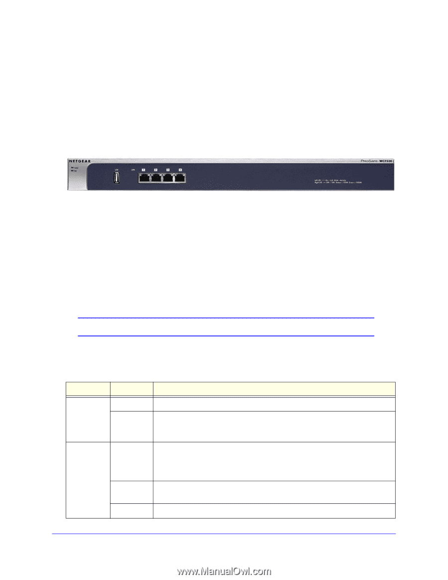
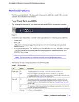
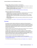
ProSafe 20-AP Wireless Controller WC7520 Reference Manual Hardware Features The front panel ports and LEDs, rear panel components, and bottom label of the wireless controller are described in this section. Front Panel Ports and LEDs The following figure shows the front panel ports and status LEDs of the wireless controller. Figure 1. From left to right, the wireless controller's front panel shows the following ports and LEDs: • Power LED. • Test LED. • USB port for external storage, for example for more floor heat maps and extended statistics history. • Four 10/100/1000 Mbps LAN Ethernet ports with RJ-45 connectors, left LEDs, and right LEDs. All Ethernet ports provide switched N-way, automatic speed-negotiating, auto MDI/MDIX technology. Note: The four ports of the wireless controller function as a single switch. The function of each LED is described in the following table: Table 1. LED Functions LED Status Power LED On Off Test LED On Off Blinking Description The green power LED should be lit when the wireless controller is on. If the power LED is not lit when the wireless controller is on, check the connections and check to see if the power outlet is controlled by a wall switch that is turned off (see Power LED Not On on page 144). The wireless controller is initializing. After approximately 2 minutes, when the wireless controller has completed its initialization, the Test LED turns off. If the Test LED remains on, the initialization has failed (see Test LED Never Turns Off on page 145). The wireless controller has completed its initialization successfully. The Test LED should be off during normal operation. Firmware is being upgraded. Chapter 1: Introduction and Overview | 10
-
 1
1 -
2
-
3
-
4
-
 5
5 -
 6
6 -
 7
7 -
 8
8 -
 9
9 -
 10
10 -
 11
11 -
 12
12 -
 13
13 -
 14
14 -
 15
15 -
16
-
17
-
18
-
19
-
20
-
21
-
22
-
23
-
24
-
25
-
26
-
27
-
28
-
29
-
30
-
31
-
32
-
33
-
34
-
35
-
36
-
37
-
38
-
39
-
40
-
41
-
42
-
43
-
44
-
45
-
46
-
47
-
48
-
49
-
50
-
51
-
52
-
53
-
54
-
55
-
56
-
57
-
58
-
59
-
60
-
61
-
62
-
63
-
64
-
65
-
66
-
67
-
68
-
69
-
70
-
71
-
72
-
73
-
74
-
75
-
76
-
77
-
78
-
79
-
80
-
81
-
82
-
83
-
84
-
85
-
86
-
87
-
88
-
89
-
90
-
91
-
92
-
93
-
94
-
95
-
96
-
97
-
98
-
99
-
100
-
101
-
102
-
103
-
104
-
105
-
106
-
107
-
108
-
109
-
110
-
111
-
112
-
113
-
114
-
115
-
116
-
117
-
118
-
119
-
120
-
121
-
122
-
123
-
124
-
125
-
126
-
127
-
128
-
129
-
130
-
131
-
132
-
133
-
134
-
135
-
136
-
137
-
138
-
139
-
140
-
141
-
142
-
143
-
144
-
145
-
146
-
147
-
148
-
149
-
150
-
151
-
152
-
153
-
154
-
155
-
156
-
157
-
158
-
159
-
160
-
161
-
162
 |
 |