Netgear WC7520 WC7520 Reference Manual - Page 41
Estimate, View Map, RF Planning, ProSafe 20-AP Wireless Controller WC7520 Reference Manual
 |
UPC - 606449072969
View all Netgear WC7520 manuals
Add to My Manuals
Save this manual to your list of manuals |
Page 41 highlights
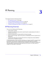
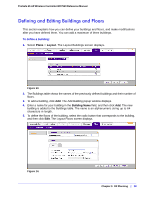
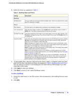
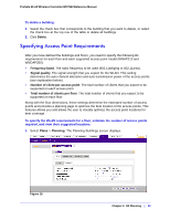
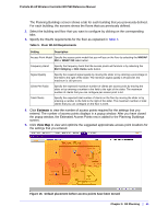
ProSafe 20-AP Wireless Controller WC7520 Reference Manual The Planning Buildings screen shows a tab for each building that you previously defined. For each building, the screens shows the floors that you previously defined. 2. Select the building and floor that you want to configure by clicking on the corresponding tabs. 3. Specify the WLAN requirements for the floor as explained in Table 5. Table 5. Floor WLAN Requirements Setting Description Access Point Model Specify the access point model that you will use on the floor by selecting the WNDAP 350 or WNAP 210 radio button. Frequency Band Specify the frequency band that the access points will function in by selecting the 802.11b/bg/ng or 802.11a/na radio button. Signal Quality Client Per Radio Total Clients Specify the required signal quality by moving the slider or by entering a percentage in the field to the right of the slider. The minimum signal quality is 25 percent, the maximum is 100 percent. Specify the expected maximum number of clients per access point by moving the slider or by entering a number in the field to the right of the slider. The maximum number of clients that you can configure per access point is 64. Specify the expected total number of clients on the floor by moving the slider or by entering a number in the field to the right of the slider. The maximum number of total clients that you can configure on the floor is 1024. 4. Click Estimate to view the number of access points required for the settings that you entered. The number of access points displays in a popup window. After you have closed the popup window, the Estimated Access Points row is added to the Planning Buildings screen. 5. Click View Map to view and optimize the suggested approximate access point locations for the settings that you entered. Figure 16. Default placement before access points have been moved Chapter 3: RF Planning | 41
-
 1
1 -
2
-
3
-
4
-
5
-
6
-
7
-
8
-
9
-
10
-
11
-
12
-
13
-
14
-
15
-
16
-
17
-
18
-
19
-
20
-
21
-
22
-
23
-
24
-
25
-
26
-
27
-
28
-
29
-
30
-
31
-
32
-
33
-
34
-
35
-
 36
36 -
 37
37 -
 38
38 -
 39
39 -
 40
40 -
 41
41 -
 42
42 -
 43
43 -
 44
44 -
 45
45 -
 46
46 -
47
-
48
-
49
-
50
-
51
-
52
-
53
-
54
-
55
-
56
-
57
-
58
-
59
-
60
-
61
-
62
-
63
-
64
-
65
-
66
-
67
-
68
-
69
-
70
-
71
-
72
-
73
-
74
-
75
-
76
-
77
-
78
-
79
-
80
-
81
-
82
-
83
-
84
-
85
-
86
-
87
-
88
-
89
-
90
-
91
-
92
-
93
-
94
-
95
-
96
-
97
-
98
-
99
-
100
-
101
-
102
-
103
-
104
-
105
-
106
-
107
-
108
-
109
-
110
-
111
-
112
-
113
-
114
-
115
-
116
-
117
-
118
-
119
-
120
-
121
-
122
-
123
-
124
-
125
-
126
-
127
-
128
-
129
-
130
-
131
-
132
-
133
-
134
-
135
-
136
-
137
-
138
-
139
-
140
-
141
-
142
-
143
-
144
-
145
-
146
-
147
-
148
-
149
-
150
-
151
-
152
-
153
-
154
-
155
-
156
-
157
-
158
-
159
-
160
-
161
-
162
 |
 |