Oki C942 C911dn/C931dn/C931DP/C941dn/C941DP/C942 Basic Users Guide - English - Page 19
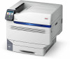
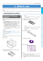
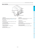
Back/Left Side, Interface, Exit Unit, Access Cover, Duplex Unit, Carrying Handles, Carrying Lever
 |
View all Oki C942 manuals
Add to My Manuals
Save this manual to your list of manuals |
Page 19 highlights
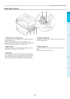
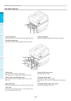
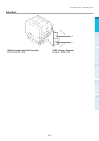
Back/Left Side Parts Nomenclature and Functions 1 Before use 2 Setting Up 3 Interface Exit Unit There are a LAN (network) interface connector and a Open this when replacing the fuser unit or transfer USB interface connector. See "Interface" (P.23) for roller unit, or to clear paper jams. the interfaces. Printing Access Cover Open this when mounting the optional built-in HDD. Duplex Unit Implements duplex printing. Basic Device Operations Carrying Handles Hold these at the same time as the carrying lever when carrying the device. Carrying Lever 4 When carrying the device, pull out this lever, and hold the carrying handles at the same time. Power Connector Connect the enclosed power cable here. Main Power Switch Turns ON and OFF the device main power supply. Left Side Cover Open this to clear paper jams. Appendix Index - 19 -
-
 1
1 -
2
-
3
-
4
-
5
-
6
-
7
-
8
-
9
-
10
-
11
-
12
-
13
-
 14
14 -
 15
15 -
 16
16 -
 17
17 -
 18
18 -
 19
19 -
 20
20 -
 21
21 -
 22
22 -
 23
23 -
 24
24 -
25
-
26
-
27
-
28
-
29
-
30
-
31
-
32
-
33
-
34
-
35
-
36
-
37
-
38
-
39
-
40
-
41
-
42
-
43
-
44
-
45
-
46
-
47
-
48
-
49
-
50
-
51
-
52
-
53
-
54
-
55
-
56
-
57
-
58
-
59
-
60
-
61
-
62
-
63
-
64
-
65
-
66
-
67
-
68
-
69
-
70
-
71
-
72
-
73
-
74
-
75
-
76
-
77
-
78
-
79
-
80
-
81
-
82
-
83
-
84
-
85
-
86
-
87
-
88
-
89
-
90
-
91
-
92
-
93
-
94
-
95
-
96
-
97
-
98
-
99
-
100
-
101
-
102
-
103
-
104
-
105
-
106
-
107
-
108
-
109
-
110
-
111
-
112
-
113
-
114
-
115
-
116
-
117
-
118
-
119
-
120
-
121
-
122
-
123
-
124
-
125
-
126
-
127
-
128
-
129
-
130
-
131
-
132
-
133
-
134
-
135
-
136
-
137
-
138
-
139
-
140
-
141
 |
 |
