Onkyo TX-DS595 Owner Manual - Page 12
Connecting your video components
 |
View all Onkyo TX-DS595 manuals
Add to My Manuals
Save this manual to your list of manuals |
Page 12 highlights
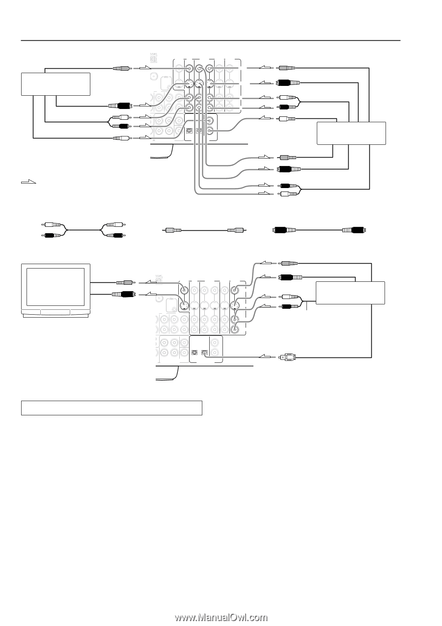
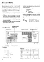
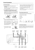
Connections Video output 4. DVD player (DVD) S video output Analog audio output Digital audio output (Coaxial) L (White) R (Red) MONITOR DVD OUT IN VIDEO 1 OUT IN VIDEO 2 VIDEO 3 IN IN VIVDIEDOEO REMOTE CONTROL NO CD OUT TAPE IN FRONT SURR CENTER L OPTICAL 1 2 COAXIAL 1 R SUB ER MULTI WOOFER UT CHANNEL INPUT 2 DIGITAL INPUT S VSIDVEIODEO L RR : Signal flow Audio connection cable Left (White) L Video connection cable V S video Video output S video output L (White) Analog audio output R (Red) Digital audio output (Coaxial) 5. VCR (VIDEO 1) Video input R (Red) S video input Analog audio input L (White) S Video connection cable Right (Red) 7. TV monitor or Projector (MONITOR OUT) R Video input S video input MONITOR DVD OUT IN VIDEO 1 OUT IN VIDEO 2 VIDEO 3 IN IN VIDEO REMOTE CONTROL NO CD OUT TAPE IN FRONT SURR CENTER L OPTICAL 1 2 COAXIAL 1 R SUB ER MULTI WOOFER UT CHANNEL INPUT 2 DIGITAL INPUT S VIDEO L R Video output S video output L (White) 6. Satelite tuner, TV, or settop box (VIDEO 2 / VIDEO 3) R (Red) Analog audio output Digital audio output (optical) Connecting your video components Below is an example of how you can connect your video components to the TX-DS595. Refer to the diagram above for the following connection examples. The flow of the video signals is as follows: • The signal that comes in from VIDEO IN is sent to VIDEO OUT. • The signal that comes in from S VIDEO IN is sent to S VIDEO OUT 4. Connecting a DVD player (DVD) If the device is equipped with an S video output terminal, connect it to the DVD S VIDEO IN terminal with an S video cable. If it does not have an S video output terminal, connect its video output terminal to the DVD VIDEO IN terminal using an RCA-type video connection cable. You do not need to connect to both the DVD S VIDEO IN and DVD VIDEO IN terminals. Using an RCA-type audio connection cable, connect the audio output terminal on the device to the audio DVD IN jacks on the TXDS595. Make sure that you properly connect the left channel to the L jack and the right channel to the R jack. 12 If the device has a digital output jack as well, be sure to also connect it to either a DIGITAL INPUT (COAXIAL) or DIGITAL INPUT (OPTICAL) jack on the TX-DS595 depending on the type of connector on the DVD player. With the initial settings of the TX-DS595, the DVD input source is set for digital input at the COAXIAL 1 jack. If the digital connection is made at a different jack, this must be changed at the setup menu: Input Setup → Audio Setup → Digital Input (see page 29). 5. Connecting a video cassette recorder (VIDEO 1) If the video cassette recorder is equipped with an S video output terminal, connect it to the S VIDEO 1 IN terminal with an S video cable. If it does not have an S video output terminal, connect its video output terminal to the VIDEO 1 IN terminal using an RCAtype video connection cable. You do not need to connect to both the S VIDEO 1 IN and VIDEO 1 IN terminals. Using an RCA-type audio connection cable, connect the audio output terminal on the video cassette recorder to the same VIDEO 1 IN audio jacks on the TX-DS595 and audio input terminal to the VIDEO 1 OUT audio jacks. Make sure that you properly connect the left channel to the L jack and the right channel to the R jack.
-
 1
1 -
2
-
3
-
4
-
5
-
6
-
 7
7 -
 8
8 -
 9
9 -
 10
10 -
 11
11 -
 12
12 -
 13
13 -
 14
14 -
 15
15 -
 16
16 -
 17
17 -
18
-
19
-
20
-
21
-
22
-
23
-
24
-
25
-
26
-
27
-
28
-
29
-
30
-
31
-
32
-
33
-
34
-
35
-
36
-
37
-
38
-
39
-
40
-
41
-
42
-
43
-
44
-
45
-
46
-
47
-
48
-
49
-
50
-
51
-
52
 |
 |