Onkyo TX-DS595 Owner Manual - Page 15
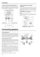
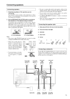
Connecting a subwoofer, Connecting the speaker cable, Connecting speakers - surround sound receiver
 |
View all Onkyo TX-DS595 manuals
Add to My Manuals
Save this manual to your list of manuals |
Page 15 highlights
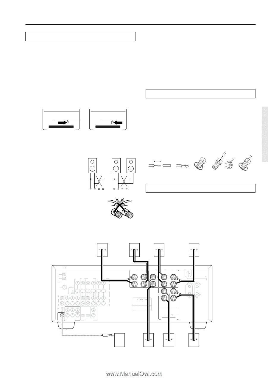
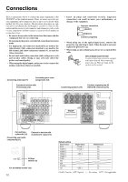
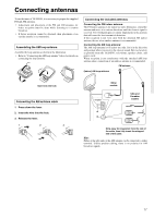
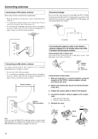
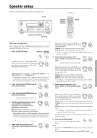
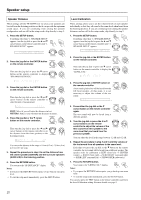
Connecting speakers Connecting speakers 1. Check the impedance of the speakers you are connecting. The TX-DS595 requires speakers with an impedance of 4 Ω or greater. Connecting speakers with an impedance of less than 4 Ω may damage the TX-DS595. 2. Set the IMPEDANCE SELECTOR switch according to the impedance of the speakers being connected. If all speakers have an impedance of 6 Ω or greater, slide the IMPEDANCE SELECTOR switch to the left (6 OHMS MIN./ SPEAKER). If one or more speakers have an impedance of less than 6 Ω, slide the IMPEDANCE SELECTOR switch to the right (4 OHMS MIN./SPEAKER). 6 OHMS MIN. / SPEAKER 4 OHMS MIN. / SPEAKER 6 OHMS MIN. / SPEAKER 4 OHMS MIN. / SPEAKER SET BEFORE POWER ON IMPEDANCE SELECTOR SET BEFORE POWER ON IMPEDANCE SELECTOR 4 Ω or above/speaker 6 Ω or above/speaker Notes: • The power to the TX-DS595 must not be turned on when changing the IMPEDANCE SELECTOR setting. • When you are using only one speaker or when you wish to listen to monaural (mono) sound, a single speaker should never be connected in parallel to both the right and left-channel terminals simultaneously. • To prevent damage to circuitry, never short-circuit the positive (+) and negative (-) speaker wire. NO! +- -+ RL +- -+ RL NO! • Be sure to connect the positive and negative cables for the speakers properly. If they are mixed up, the left and right signals will be reversed and the audio will sound unnatural. • Do not connect more than one speaker cable to one speaker terminal. Doing so may damage the TX-DS595. • Use FRONT SPEAKERS B terminals to connect a second pair of front speakers. • When you listen to surround audio or select Multichannel, be sure to turn on SPEAKERS A. Connecting the speaker cable 1. Strip away 5/8 inch (15 mm) of wire insulation. 2. Twist wire ends very tight. 3. Unscrew 4. Insert wire 5. Screw 1 2 3 4 5 15mm (5/8") Connecting a subwoofer Use the PRE OUT SUBWOOFER jack to connect a subwoofer with a built-in power amplifier. If your subwoofer does not have a built-in amplifier, connect an amplifier to the PRE OUT SUBWOOFER jack and the subwoofer to the amplifier. Front right speaker A Front left speaker A Surround right speaker Surround left speaker ANTENNA AM MONITOR DVD OUT IN VIDEO 1 OUT IN VIDEO 2 VIDEO 3 IN IN VIDEO FM 75 REMOTE CONTROL S VIDEO PHONO CD OUT TAPE IN L L R R GND FRONT SURR CENTER L OPTICAL 1 2 COAXIAL 1 SUBWOOFER PRE OUT R SUB MULTI WOOFER CHANNEL INPUT 2 DIGITAL INPUT FRONT SPEAKERS A R L CENTER SPEAKER SURROUND SPEAKERS R L FRONT SPEAKERS B AV RECEIVER MODEL NO. TX-DS595 R L CAUTION: SEE INSTRUCTION MANUAL FOR CORRECT SETTING. 6 OHMS MIN. / SPEAKER 4 OHMS MIN. / SPEAKER SET BEFORE POWER ON IMPEDANCE SELECTOR AC OUTLETS AC 230-240V 50 Hz SWITCHED TOTAL 100W MAX. Subwoofer Center Front right Front left speaker speaker B speaker B 15
-
 1
1 -
2
-
3
-
4
-
5
-
6
-
7
-
8
-
9
-
 10
10 -
 11
11 -
 12
12 -
 13
13 -
 14
14 -
 15
15 -
 16
16 -
 17
17 -
 18
18 -
 19
19 -
 20
20 -
21
-
22
-
23
-
24
-
25
-
26
-
27
-
28
-
29
-
30
-
31
-
32
-
33
-
34
-
35
-
36
-
37
-
38
-
39
-
40
-
41
-
42
-
43
-
44
-
45
-
46
-
47
-
48
-
49
-
50
-
51
-
52
 |
 |