Panasonic KX-TDA600 Installation Manual - Page 102
Frame Ground Connection
 |
UPC - 037988851775
View all Panasonic KX-TDA600 manuals
Add to My Manuals
Save this manual to your list of manuals |
Page 102 highlights
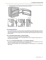
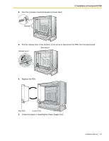
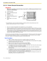
2.2 Installation of the Hybrid IP-PBX 2.2.10 Frame Ground Connection IMPORTANT Make sure to separately connect the frame of each shelf to a different ground terminal. Do not connect it to other shelves. 1. Loosen the screw. 2. Insert a grounding wire (usersupplied)*. 3. Tighten the screw. 4. Connect the grounding wire to ground. 5. Repeat steps 1 to 4 for each shelf. Screw Grounding wire To ground * For grounding wire, green-and-yellow insulation is required, and the cross-sectional area of the conductor must be more than 0.75 mm2 or 18 AWG. • Be sure to comply with applicable local regulations (e.g., laws, guidelines). • Proper grounding (connection to ground) is very important to protect the Hybrid IP-PBX from the bad effects of external noise or to reduce the risk to the user of electrocution in the case of a lightning strike. • The grounding wire of the AC cable has an effect against external noise and lightning strikes, but it may not be enough to protect the Hybrid IP-PBX. A permanent connection between ground and the ground terminal of each Hybrid IP-PBX must be made. In most of the continental United States, the ground provided by the "Third wire ground" at the commercial power outlet will be satisfactory. However, in a small percentage of cases this ground may be installed incorrectly. Therefore, the following test procedure should be performed. Test Procedure 1. Obtain a suitable voltmeter and set it for a possible reading of up to 250 V AC. 2. Connect the meter probes between the 2 main AC voltage points on the wall outlet. The reading obtained should be 108 V AC to 132 V AC. 3. Move one of the meter probes to the 3rd prong terminal (GND). Either the same reading or a reading of 0 volt should be obtained. 4. If a reading of 0 volt at one terminal and a reading of 108 V AC to 132 V AC at the other terminal is not obtained, the outlet is not properly grounded. This condition should be corrected by a qualified electrician (per article 250 of the National Electrical Code). 5. If a reading of 0 volt at one terminal and a reading of 108 V AC to 132 V AC at the other terminal is obtained, then set the meter to the "OHMS/RX1" scale, place one probe at the GND Terminal and the other probe at the terminal which gave a reading of 0 volt. A reading of less than 1 ohm should be obtained. If the reading is not obtained, the outlet is not adequately grounded. See qualified electrician. 102 Installation Manual
-
 1
1 -
2
-
3
-
4
-
5
-
6
-
7
-
8
-
9
-
10
-
11
-
12
-
13
-
14
-
15
-
16
-
17
-
18
-
19
-
20
-
21
-
22
-
23
-
24
-
25
-
26
-
27
-
28
-
29
-
30
-
31
-
32
-
33
-
34
-
35
-
36
-
37
-
38
-
39
-
40
-
41
-
42
-
43
-
44
-
45
-
46
-
47
-
48
-
49
-
50
-
51
-
52
-
53
-
54
-
55
-
56
-
57
-
58
-
59
-
60
-
61
-
62
-
63
-
64
-
65
-
66
-
67
-
68
-
69
-
70
-
71
-
72
-
73
-
74
-
75
-
76
-
77
-
78
-
79
-
80
-
81
-
82
-
83
-
84
-
85
-
86
-
87
-
88
-
89
-
90
-
91
-
92
-
93
-
94
-
95
-
96
-
 97
97 -
 98
98 -
 99
99 -
 100
100 -
 101
101 -
 102
102 -
 103
103 -
 104
104 -
 105
105 -
 106
106 -
 107
107 -
108
-
109
-
110
-
111
-
112
-
113
-
114
-
115
-
116
-
117
-
118
-
119
-
120
-
121
-
122
-
123
-
124
-
125
-
126
-
127
-
128
-
129
-
130
-
131
-
132
-
133
-
134
-
135
-
136
-
137
-
138
-
139
-
140
-
141
-
142
-
143
-
144
-
145
-
146
-
147
-
148
-
149
-
150
-
151
-
152
-
153
-
154
-
155
-
156
-
157
-
158
-
159
-
160
-
161
-
162
-
163
-
164
-
165
-
166
-
167
-
168
-
169
-
170
-
171
-
172
-
173
-
174
-
175
-
176
-
177
-
178
-
179
-
180
-
181
-
182
-
183
-
184
-
185
-
186
-
187
-
188
-
189
-
190
-
191
-
192
-
193
-
194
-
195
-
196
-
197
-
198
-
199
-
200
-
201
-
202
-
203
-
204
-
205
-
206
-
207
-
208
-
209
-
210
-
211
-
212
-
213
-
214
-
215
-
216
-
217
-
218
-
219
-
220
-
221
-
222
-
223
-
224
-
225
-
226
-
227
-
228
-
229
-
230
-
231
-
232
 |
 |
