Panasonic KX-TDA600 Installation Manual - Page 150
Ring port 15
 |
UPC - 037988851775
View all Panasonic KX-TDA600 manuals
Add to My Manuals
Save this manual to your list of manuals |
Page 150 highlights
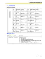
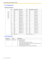
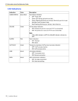
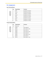
2.7 Information about the Extension Cards Pin Assignments Amphenol Connector 50 25 26 1 No. Signal Name Function 1 RA Ring port 1 2 RB Ring port 2 3 RC Ring port 3 4 RD Ring port 4 5 RE Ring port 5 6 RF Ring port 6 7 RG Ring port 7 8 RH Ring port 8 9 RI Ring port 9 10 RJ Ring port 10 11 RK Ring port 11 12 RL Ring port 12 13 RM Ring port 13 14 RN Ring port 14 15 RO Ring port 15 16 RP Ring port 16 17-25 Reserved - No. Signal Name Function 26 TA Tip port 1 27 TB Tip port 2 28 TC Tip port 3 29 TD Tip port 4 30 TE Tip port 5 31 TF Tip port 6 32 TG Tip port 7 33 TH Tip port 8 34 TI Tip port 9 35 TJ Tip port 10 36 TK Tip port 11 37 TL Tip port 12 38 TM Tip port 13 39 TN Tip port 14 40 TO Tip port 15 41 TP Tip port 16 42-50 Reserved - LED Indications Indication CARD STATUS Color Green/Red Description Card status indication • OFF: Power Off • Green ON: Normal (all ports are idle) • Green Flashing (60 times per minute): Normal (a port is in use) • Red ON: Fault (includes reset) • Red Flashing (60 times per minute): Out of Service 150 Installation Manual
-
 1
1 -
2
-
3
-
4
-
5
-
6
-
7
-
8
-
9
-
10
-
11
-
12
-
13
-
14
-
15
-
16
-
17
-
18
-
19
-
20
-
21
-
22
-
23
-
24
-
25
-
26
-
27
-
28
-
29
-
30
-
31
-
32
-
33
-
34
-
35
-
36
-
37
-
38
-
39
-
40
-
41
-
42
-
43
-
44
-
45
-
46
-
47
-
48
-
49
-
50
-
51
-
52
-
53
-
54
-
55
-
56
-
57
-
58
-
59
-
60
-
61
-
62
-
63
-
64
-
65
-
66
-
67
-
68
-
69
-
70
-
71
-
72
-
73
-
74
-
75
-
76
-
77
-
78
-
79
-
80
-
81
-
82
-
83
-
84
-
85
-
86
-
87
-
88
-
89
-
90
-
91
-
92
-
93
-
94
-
95
-
96
-
97
-
98
-
99
-
100
-
101
-
102
-
103
-
104
-
105
-
106
-
107
-
108
-
109
-
110
-
111
-
112
-
113
-
114
-
115
-
116
-
117
-
118
-
119
-
120
-
121
-
122
-
123
-
124
-
125
-
126
-
127
-
128
-
129
-
130
-
131
-
132
-
133
-
134
-
135
-
136
-
137
-
138
-
139
-
140
-
141
-
142
-
143
-
144
-
 145
145 -
 146
146 -
 147
147 -
 148
148 -
 149
149 -
 150
150 -
 151
151 -
 152
152 -
 153
153 -
 154
154 -
 155
155 -
156
-
157
-
158
-
159
-
160
-
161
-
162
-
163
-
164
-
165
-
166
-
167
-
168
-
169
-
170
-
171
-
172
-
173
-
174
-
175
-
176
-
177
-
178
-
179
-
180
-
181
-
182
-
183
-
184
-
185
-
186
-
187
-
188
-
189
-
190
-
191
-
192
-
193
-
194
-
195
-
196
-
197
-
198
-
199
-
200
-
201
-
202
-
203
-
204
-
205
-
206
-
207
-
208
-
209
-
210
-
211
-
212
-
213
-
214
-
215
-
216
-
217
-
218
-
219
-
220
-
221
-
222
-
223
-
224
-
225
-
226
-
227
-
228
-
229
-
230
-
231
-
232
 |
 |
