Panasonic KX-TDA600 Installation Manual - Page 158
External Sensor, External Relay
 |
UPC - 037988851775
View all Panasonic KX-TDA600 manuals
Add to My Manuals
Save this manual to your list of manuals |
Page 158 highlights
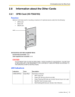
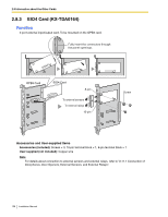
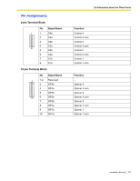
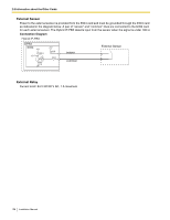
2.8 Information about the Other Cards External Sensor Power to the external sensor is provided from the EIO4 card and must be grounded through the EIO4 card as indicated in the diagram below. A pair of "sensor" and "common" lines are connected to the EIO4 card for each external sensor. The Hybrid IP-PBX detects input from the sensor when the signal is under 100 Ω. Connection Diagram Hybrid IP-PBX OPB3 EIO4 +5V 10K I/O 4.7K 4.7K +5V 33 33 sensor common External Sensor External Relay Current Limit: 24 V DC/30 V AC, 1 A maximum 158 Installation Manual
-
 1
1 -
2
-
3
-
4
-
5
-
6
-
7
-
8
-
9
-
10
-
11
-
12
-
13
-
14
-
15
-
16
-
17
-
18
-
19
-
20
-
21
-
22
-
23
-
24
-
25
-
26
-
27
-
28
-
29
-
30
-
31
-
32
-
33
-
34
-
35
-
36
-
37
-
38
-
39
-
40
-
41
-
42
-
43
-
44
-
45
-
46
-
47
-
48
-
49
-
50
-
51
-
52
-
53
-
54
-
55
-
56
-
57
-
58
-
59
-
60
-
61
-
62
-
63
-
64
-
65
-
66
-
67
-
68
-
69
-
70
-
71
-
72
-
73
-
74
-
75
-
76
-
77
-
78
-
79
-
80
-
81
-
82
-
83
-
84
-
85
-
86
-
87
-
88
-
89
-
90
-
91
-
92
-
93
-
94
-
95
-
96
-
97
-
98
-
99
-
100
-
101
-
102
-
103
-
104
-
105
-
106
-
107
-
108
-
109
-
110
-
111
-
112
-
113
-
114
-
115
-
116
-
117
-
118
-
119
-
120
-
121
-
122
-
123
-
124
-
125
-
126
-
127
-
128
-
129
-
130
-
131
-
132
-
133
-
134
-
135
-
136
-
137
-
138
-
139
-
140
-
141
-
142
-
143
-
144
-
145
-
146
-
147
-
148
-
149
-
150
-
151
-
152
-
 153
153 -
 154
154 -
 155
155 -
 156
156 -
 157
157 -
 158
158 -
 159
159 -
 160
160 -
 161
161 -
 162
162 -
 163
163 -
164
-
165
-
166
-
167
-
168
-
169
-
170
-
171
-
172
-
173
-
174
-
175
-
176
-
177
-
178
-
179
-
180
-
181
-
182
-
183
-
184
-
185
-
186
-
187
-
188
-
189
-
190
-
191
-
192
-
193
-
194
-
195
-
196
-
197
-
198
-
199
-
200
-
201
-
202
-
203
-
204
-
205
-
206
-
207
-
208
-
209
-
210
-
211
-
212
-
213
-
214
-
215
-
216
-
217
-
218
-
219
-
220
-
221
-
222
-
223
-
224
-
225
-
226
-
227
-
228
-
229
-
230
-
231
-
232
 |
 |

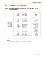
2.8 Information about the Other Cards
158
Installation Manual
External Sensor
Power to the external sensor is provided from the EIO4 card and must be grounded through the EIO4 card
as indicated in the diagram below. A pair of "sensor" and "common" lines are connected to the EIO4 card
for each external sensor. The Hybrid IP-PBX detects input from the sensor when the signal is under 100
Ω
.
Connection Diagram
External Relay
Current Limit: 24 V DC/30 V AC, 1 A maximum
External Sensor
sensor
common
I/O
EIO4
OPB3
Hybrid IP-PBX
+5V
+5V
10K
33
33
4.7K
4.7K