Panasonic PT-DW100U Dlp Projector - Multi Language - Page 14
Projector Main Unit
 |
View all Panasonic PT-DW100U manuals
Add to My Manuals
Save this manual to your list of manuals |
Page 14 highlights
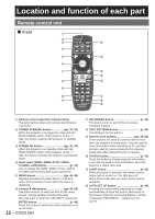
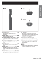
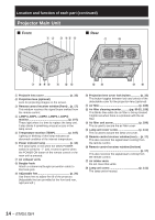
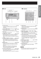
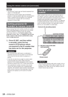
Location and function of each part (continued) Projector Main Unit ■ Front ■ Rear # $ % &( ) * 2 * + -. / 0 1 34 56 # Projectin lens cover p. 33) $ Projection lens (optional) Lens for projecting images on the screen. % Remote control receiver window (front) .. (p. 17) This window receives the signal beam emitted from the remote control. & LAMP (LAMP1, LAMP2, LAMP3, LAMP4) monitor p. 107) These light when it is time to replace the lamp unit. It also blinks if something unusual occurs in the lamp circuit. ( Temperature monitor (TEMP p. 107) Lighting or blinking of this lamp indicates an abnormal condition of the internal temperature. ) Power indicator lamp p. 34) The lamp lights in red when the MAIN POWER switch is turned to " l " (on). It turns to green when the POWER ON button of the remote control or the main unit is pressed. * Air exhaust vents + Burglar hook Attach a commercial burglar prevention cable to this hook port. - Adjustable feet p. 20) Use these feet to adjust the tilt of the projector. (Adjustable feet are provided at the front and rear, right and left.) . Projection lens cover lock button p. 33) This button toggles between lock and unlock of the detachable cover for the projection lens (optional). / Air filter p. 108) 0 Air filter cleaning monitor pp. 80-81, 108) This blinks blue while the air filter is being cleaned. It lights red when there is a problem with the air filter. 1 Air filter unit screw p. 108) This is used to secure the air filter cover. 2 Lamp unit cover screw p. 111) This is used to secure the lamp unit cover. 3 Remote control receiver window (rear).... (p. 17) This also receives the signal beam coming from the remote control. 4 Remote control receiver window (bottom) p. 17) This also receives the signal beam coming from the remote control. 5 Air intake vents Do not cover this vents. 6 Lamp unit cover p. 111) The lamp unit is housed. 14 - ENGLISH
-
 1
1 -
2
-
3
-
4
-
5
-
6
-
7
-
8
-
 9
9 -
 10
10 -
 11
11 -
 12
12 -
 13
13 -
 14
14 -
 15
15 -
 16
16 -
 17
17 -
 18
18 -
 19
19 -
20
-
21
-
22
-
23
-
24
-
25
-
26
-
27
-
28
-
29
-
30
-
31
-
32
-
33
-
34
-
35
-
36
-
37
-
38
-
39
-
40
-
41
-
42
-
43
-
44
-
45
-
46
-
47
-
48
-
49
-
50
-
51
-
52
-
53
-
54
-
55
-
56
-
57
-
58
-
59
-
60
-
61
-
62
-
63
-
64
-
65
-
66
-
67
-
68
-
69
-
70
-
71
-
72
-
73
-
74
-
75
-
76
-
77
-
78
-
79
-
80
-
81
-
82
-
83
-
84
-
85
-
86
-
87
-
88
-
89
-
90
-
91
-
92
-
93
-
94
-
95
-
96
-
97
-
98
-
99
-
100
-
101
-
102
-
103
-
104
-
105
-
106
-
107
-
108
-
109
-
110
-
111
-
112
-
113
-
114
-
115
-
116
-
117
-
118
-
119
-
120
-
121
-
122
-
123
-
124
-
125
-
126
-
127
-
128
-
129
-
130
-
131
-
132
 |
 |
