Panasonic PT-DW100U Dlp Projector - Multi Language - Page 28
Installation of input module optional continued, Procedure of installation, Remove the slot cover.
 |
View all Panasonic PT-DW100U manuals
Add to My Manuals
Save this manual to your list of manuals |
Page 28 highlights
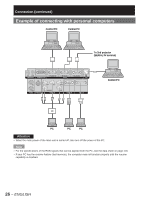
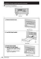
Installation of input module (optional) (continued) ■ Procedure of installation Disconnect the power before installing the input module. IN OUT REMOTE 1 REMOTE 2 IN RS-232C IN RS-422 IN SERIAL RS-422 OUT LAN IN OUT VIDEO S-VIDEO IN R/PR G/Y SYNC/HD RGB 1 IN B/PB VD RGB 2 IN DVI-D IN MENU POWER ON STANDBY VIDEO S-VIDEO RGB1 RGB2 AUTO SETUP DVI-D AUX LENS ENTER SHUTTER LIGHT ON OFF AC IN OFF ON MAIN POWER Slot Cover 1. Remove the slot cover. 2. Insert the input module. Remove 2 screws. 3. Fix the input module. 4. Register the input signal. • This projector needs to register the type of input signal after the installation of the input module. • For details on the registration of the input signals, refer to pages 40-42. 28 - ENGLISH Slot Input module Tighten the two screws.
-
 1
1 -
2
-
3
-
4
-
5
-
6
-
7
-
8
-
9
-
10
-
11
-
12
-
13
-
14
-
15
-
16
-
17
-
18
-
19
-
20
-
21
-
22
-
 23
23 -
 24
24 -
 25
25 -
 26
26 -
 27
27 -
 28
28 -
 29
29 -
 30
30 -
 31
31 -
 32
32 -
 33
33 -
34
-
35
-
36
-
37
-
38
-
39
-
40
-
41
-
42
-
43
-
44
-
45
-
46
-
47
-
48
-
49
-
50
-
51
-
52
-
53
-
54
-
55
-
56
-
57
-
58
-
59
-
60
-
61
-
62
-
63
-
64
-
65
-
66
-
67
-
68
-
69
-
70
-
71
-
72
-
73
-
74
-
75
-
76
-
77
-
78
-
79
-
80
-
81
-
82
-
83
-
84
-
85
-
86
-
87
-
88
-
89
-
90
-
91
-
92
-
93
-
94
-
95
-
96
-
97
-
98
-
99
-
100
-
101
-
102
-
103
-
104
-
105
-
106
-
107
-
108
-
109
-
110
-
111
-
112
-
113
-
114
-
115
-
116
-
117
-
118
-
119
-
120
-
121
-
122
-
123
-
124
-
125
-
126
-
127
-
128
-
129
-
130
-
131
-
132
 |
 |
